This thread has been locked.

If you have a related question, please click the "Ask a related question" button in the top right corner. The newly created question will be automatically linked to this question.

AMC1305M25: Regarding EMI issues during the use of AMC1305F25DWR

Part Number: AMC1305M25


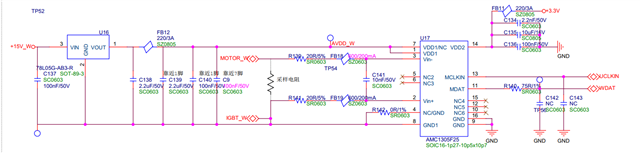
1. Application circuit diagram:

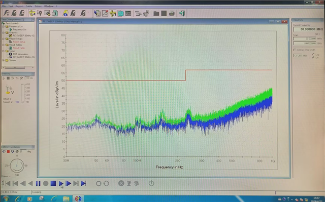
2. RE radiation (only switching power supply operates, source end disconnected uCLK)

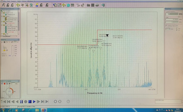
3、RE辐射(开关电源工作同时AMC1305F25DWR工作,CLK时钟频率20MHz

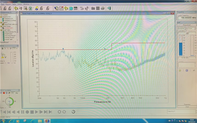
4. RE radiation (connected to peripheral cables, under normal operating conditions) exceeds the limit value

frequency of 20MHz. According to the points calibrated in Figure 3, it can be seen that the high-energy spectrum has an equal spacing of 10MHz. In addition, we removed the external cable, turned off the AMC1305 clock, and only kept the switching power supply working. The background spectrum was measured to be relatively clean. Then, we restored the AMC1305 clock to start working sampling, and found that the high-energy 10MHz spectrum had already been generated. We hope to obtain a relatively effective solution without affecting signal quality. We can provide PCB layout suggestions and make changes accordingly.

  • Hi, 

    We've addressed this question with our internal field team. 

    The AMC1305 is an older generation isolated modulator product and the customer may see some benefit by changing to a newer device with lower radiated emissions such as the AMC1306. 

    Furthermore, I see the ground trace is routed next to the clock and data signals. There may be some improvement by routing ground directly under clock and data.

    There may also be benefit to analyzing the clock and data signals directly with an oscilloscope and slowing down the rising/falling edges of the digital signals with RC filters may improve emissions as well. 

    There are many information sources online in regards to general radiated emissions.