This thread has been locked.

If you have a related question, please click the "Ask a related question" button in the top right corner. The newly created question will be automatically linked to this question.

AFE5816: AFE5816 Ideal clock requirement

Part Number: AFE5816

Tool/software:

Hi, everyone.

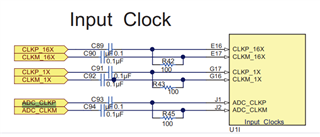
I am developing a medical ultrasound system using the AFE5816 device. I need to digitize the received signals using the AFE5816, and I have a question regarding the clock requirements stated in the datasheet.

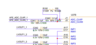
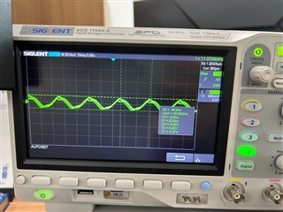
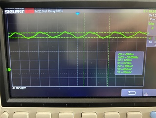
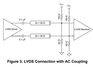
I plan to use LVDS or LVPECL, and the clock requirements mention a Vpp value when AC-coupled, while the common mode voltage is internally set to 1V. The clock provided by my board is as shown in the image below. Even though the Vpp is satisfied, could there be an issue because it is not AC-coupled?

And, Can you tell me minimum value of Vpp for normal opertaion in LVDS and LVCEPL?

In datasheet, there is a typical value only.

Thank you 

  • There 's mistake in my question. In datasheet , common mode voltage is internally set to 0.7V.

  • Hi,

    We strongly recommend to use ac coupling . Device internal common mode for clock and standard lvds driver common mode is not matched . Also this common mode also effects the performance .  All the characterization of device is done with ac coupling . 

    Is there any specific reason for choosing dc coupling ? When you do ac coupling swing requirement is as per standard lvds/lvpecl .

  • Actually, I didn't realize that all of the values in datasheet is ac-coupled case.

    So I tried to ac coupling my clock signal. 

    This is my AFE clock circuit.

    I checked each signal with an oscilloscope:

    1. After removing C340 and C341, checking the AFE_ADC_CLKP_1 and AFE_ADC_CLKN_1 signals confirms that AC coupling is not present, and the common mode voltage is 1.2V with a 550mVpp swing.

           2. After reattaching the capacitors and ensuring they are not connected to R192 by lifting one pad, checking after the capacitor confirms that AC coupling is present, as shown in the figure below. Therefore, there is no DC offset, and it has a swing of about 550mVpp.

    However, when connected to the termination resistor, it is confirmed to have a common mode voltage of 750mV due to the internally set common voltage, as shown in the picture below. However, the voltage swing significantly decreases from 550mVpp to about 100mVpp.

    Is this issue caused by the mismatch between the value of the oscillator generating the clock and the termination resistor? The clock is generated by LVCMOS33 in the FPGA and converted to an LVDS clock through the ZL40215 buffer.

  • I'm wondering about the exact desired value at J1, J2 pin of AFE5816

    Please let me know.

    Also typical LVDS swing value is 350mVpp at AFE5816 datasheet

    But, my clock buffer generates 550mVpp differential swing. Is it okay for operating?

  • Also, Do i need to DC balancing with the circuit like below?? Or my circuit is ok for operating?

  • You can refere to datasheet section 8.3.6.4 CW Clock Selection for example configuration.

    One difference I see between your configuration and datasheet is the location of 100Ohm termination and coupling cap.

    You dont have to give DC balancing as the common mode of ADC_CLK is determined by device.

  • As you can see in my figure above,

    my clock circuit dont have dc balancing circuit

    im just wondering if i need that.

    Thanks for your response

    My main question is about the differential swing.

    my clock has about 550mVpp differential swing but after connecting with afe, clock has about 100mVpp swing

    Is that okay for operating afe correctly?

    And is that problem caused by the resistance difference?

  • According to the AFE5816EVM, location of resistor and coupling cap is same as my circuit.

    What is the correct method??

    And again ,

    my clock has about 550mVpp differential swing but after connecting with afe, clock has about 100mVpp swing

    Is that okay for operating afe correctly?

  • You can refere to datasheet section 8.3.6.4 CW Clock Selection for example configuration.

    Here the cap is coming close to device .