- Ask a related questionWhat is a related question?A related question is a question created from another question. When the related question is created, it will be automatically linked to the original question.
Tool/software:
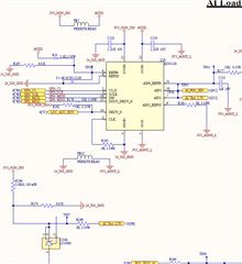
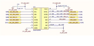
We have designed custom PCB with ADS1120 for Load Cell and Position Sensor Measurements.
Once the Board Power On , the DRDY pin does not go low and is always High.
I have followed example code mentioned in Datasheet but i read 0xff from the ADC registers.
Set CS to the device low; Delay for a minimum of td(CSSC);
Send the RESET command (06h) to make sure the device is properly reset after power-up;
Delay for a minimum of 50 µs + 32 · t(CLK);
Write the respective register configuration with the WREG command (43h, 08h, 04h, 10h, and 00h); - I am doing single write's here instead of Bulk Writes.
As an optional sanity check, read back all configuration registers with the RREG command (23h);- I am doing single read's here
Send the START/SYNC command (08h) to start converting in continuous conversion mode; Delay for a minimum of td(SCCS);
Clear CS to high (resets the serial interface);
Attaching Schematic :