This thread has been locked.

If you have a related question, please click the "Ask a related question" button in the top right corner. The newly created question will be automatically linked to this question.

ADS131A04: ADS131A04 External Protection

Part Number: ADS131A04
Other Parts Discussed in Thread: TLV171

Tool/software:

Hello, everyone,

I'm working with the ADC converter ADS131A04 in unipolar analog power supply mode (3.3V) with negative charge pump enabled. The purpose of the work is to measure voltage and current, something very close to a power meter. The datasheet (SBAS590E) page 77 (1° LINK) shows the basic circuit I'm implementing. In this configuration, what would be the best configuration for additional external protection? My concern is the protection of the current analog inputs, I'm reading values from a CT (1:2000). In another reference designer page  (2°LINK)   the TVS0500DRVR is placed but the breakdown voltage is in the 5V range. With this voltage the ADS131A04 can be damaged because the maximum voltage at the analog input is 3.6V. Am I right? Which other TVS would you recommend for my application?

1° LINK
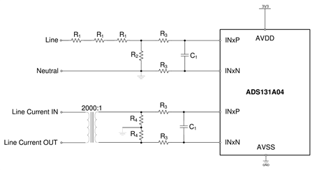
2° LINK

Thanks for your help,

Alanderson

  • Hi Alanderson,

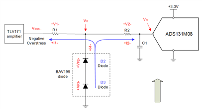
    Thanks for choosing TI ADCs. ADS131A04 has a similar input circuity as ADS131M0x ADCs, a negative charge pump is integrated on every input channel pin so the input signal can be negative under the ground, an internal ESD diode is designed between AINx pin and AVDD but no ESD diode between AINx pin and the ground. The following app note could be a good reference for you in terms of ADC input protection.

    Circuit for protecting ADS131M0x ADC from electrical overstress

    The Absolute Maximum Ratings table in the ADS131A04 datasheet shows the stress specifications, the safety of the ADC can not be guaranteed if the voltage or the current to the ADC exceeds the specifications in this table. Your understanding is correct, 3.6V is the maximum voltage that can be applied to ADS131A04 input without a damage if the AVDD of your ADC is 3.3V.

    BR,

    Dale

  • Hello, Dale,

    Thanks for your help. In the article you sent me as a reference the formulas for R1 and R2 are based on the outputs of operational amplifiers (TLV171) where the output currents and voltages are well defined. How can I calculate the values when the overvoltage event is coming from a current transformer? In the configuration below, the signal comes from a single line.


    How can I connect in the configuration below? How can I connect in the configuration below? To the AINX_N and AINX_P lines.

    Excuse my lack of understanding on the subject,

    Thanks for your help,

    Alanderson

  • Hi Alanderson,

    Your question: How can I calculate the values when the overvoltage event is coming from a current transformer? In the configuration below, the signal comes from a single line.

    DL: the calculation of resistor value and the selection of protection diode depends on the overstress voltage which could be seen in your system. Since your transformer is a kind of isolation, is there any special reason you want to add a protection circuitry? are you considering the protection against transient signals?

    You questions: How can I connect in the configuration below? How can I connect in the configuration below? To the AINX_N and AINX_P lines.

    DL: the app note only shows the protection circuit for one analog input as an example. If you input is a differential signal and both AINx_P and AINx_N pins could have a overdriven situation, then you should consider the same protection technique on all of these pins.

    BR,

    Dale

  • Hello, Dale

    That's right. It's the transient calculation, which is totally value-free. I think we have to set a maximum value and hope we're right.
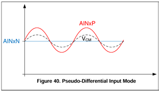
    The ADC131A4 datasheet talks about the Pseudo-Differential configuration (LINK), page 30. The AINxN bus will be the reference for connecting the circuit described.

    I'm also reading about a TVS whose Clamping Voltage is 3.6V. Maybe you can help!

    Thanks for your help,

    Alanderson