This thread has been locked.

If you have a related question, please click the "Ask a related question" button in the top right corner. The newly created question will be automatically linked to this question.

ADS1298: Trouble with SPI communication

Other Parts Discussed in Thread: ADS1298

Tool/software:

Dear all, 


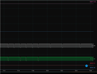
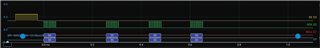
I am having issues communication with my ADS1298 device via SPI with my adafruit ESP32 Feather V2. I have followed all the debug steps mentioned in the Forum. I have also used the oscilloscope to analyse the signals and the DRDY, CS, and SCLK signals all seem to be as expected. I am using the code located at (https://github.com/ferdinandkeil/ADS129X/tree/master/examples/Serial_EMG) and I also tried the code located at (https://github.com/adamfeuer/ADS129x-tools/tree/master/ads1298_hello_world) and the ID register does not read back correctly. Additionally, I tried a simple code just to configure the communication between the ADS1298 and the microcontroller but there still seem to be no communication between the devices. I have checked the pin configurations several times as well to make sure I configured them correctly.  Could you please guide me on what could be the possible issue?

Thanks in advance.

Best, 

Abdelrahman

  • Hello Abdelrahman,

    Thank you for your post. Can you share a logic analyzer capture of the SPI frame which reads the Device ID register? 

    Regards,

    Ryan

  • ADS129X_File.zip

    Dear Ryan,

    Thank you for your quick response. I have attached a ZIP file that includes the code, along with a snippet from the logic analyser for your reference.

    In my code, I am utilizing HSPI commands since I'm working with the HSPI pins on the ESP32. I would greatly appreciate it if you could review the attached files and provide further guidance on the issue.

    Best,
    Abdelrahman

  • Thanks, Abdelrahman.

    This does not look like the SPI protocol was set up correctly. I do not see SCLK toggling within each frame (time during nCS is low). There is also no activity on MISO, MOSI, or nDRDY.

    Unfortunately, we cannot provide support for configuring the ESP32 itself. I do not see why this board would be incompatible, so please adjust your HSPI config settings and let me know the result. You can refer to Figure 1 and Sections 7.6-7.7 for relevant timing and switching characteristics for the ADS1298 interface.

    Regards,

    Ryan

  • Hi Ryan, 

    I adjusted the SPI configuration and now the SCLK when the nCS is low. Additionally, I am able to send commands with MOSI but there is no activity on MISO. I uploaded a zip folder from the images of the logic analyser + the code. I would appreciate if you can provide me with further guidance. 

    #include <SPI.h>
    
    // Define the SPI pins for HSPI (on ESP32 or custom setup)
    #define HSPI_MISO   12
    #define HSPI_MOSI   13
    #define HSPI_SCLK   14
    #define HSPI_SS     15
    #define PWDN_PIN    32  // Define the PWDN control pin for ADS1298
    
    static const int spiClk = 150000; // 150 kHz clock speed
    
    // Uninitialized pointer to SPI object
    SPIClass *hspi = NULL;
    
    void setup() {
      // Initialize serial for debugging
      Serial.begin(115200);
      
      // Initialize instance of the SPIClass attached to HSPI
      hspi = new SPIClass(HSPI);
    
      // Initialize SPI bus with default pins SCLK = 14, MISO = 12, MOSI = 13, SS = 15
      hspi->begin(HSPI_SCLK, HSPI_MISO, HSPI_MOSI, HSPI_SS);
    
      // Set SS as output and set it high to start with (deselect)
      pinMode(HSPI_SS, OUTPUT);
      digitalWrite(HSPI_SS, HIGH);
    
      // Set up the PWDN control pin
      pinMode(PWDN_PIN, OUTPUT);
    
      // Power up the ADS1298 by setting PWDN pin HIGH
      digitalWrite(PWDN_PIN, HIGH);
      delay(100);  // Small delay to ensure the device powers up
    
      Serial.println("ADS1298 Powered Up");
    }
    
    void loop() {
      // Optionally: Add logic to enter Power-Down mode (if needed)
      // digitalWrite(PWDN_PIN, LOW);  // Pull LOW to enter Power-Down mode
      // delay(1000);  // Delay to simulate Power-Down mode
    
      byte commands[] = {0x0A, 0x20, 0x00};  // Array of commands
      byte response;                         // Variable to hold the response from the slave
      byte deviceID = 0x00;                  // Device ID
    
      // Start SPI transaction for sending the commands
      hspi->beginTransaction(SPISettings(spiClk, MSBFIRST, SPI_MODE1));
    
      // Pull SS low to select the slave
      digitalWrite(HSPI_SS, LOW);
      delayMicroseconds(10);  // Small delay to stabilize the signal
      
      // Send the command bytes to the slave
      for (int i = 0; i < sizeof(commands) / sizeof(commands[0]); i++) {
        response = hspi->transfer(commands[i]);  // Send and receive at the same time
        Serial.print("Sent command: ");
        Serial.println(commands[i], HEX);
        Serial.print("Response from slave: ");
        Serial.println(response, HEX);  // Display the response (if the slave sends any data back)
      }
    
      // Send and receive device ID
      response = hspi->transfer(deviceID);  // Send and receive at the same time
      Serial.print("Sent device ID command: ");
      Serial.println(deviceID, HEX);
      
      Serial.print("Response from slave: ");
      Serial.println(response, HEX);  // Display the response (if the slave sends any data back)
    
      // Pull SS high to deselect the slave
      digitalWrite(HSPI_SS, HIGH);
    
      // End SPI transaction
      hspi->endTransaction();
    
      delay(1000); // Wait for a second before the next loop
    }
    TI_Support.zip

  • Hi Abdelrahman,

    In this frame, you are sending the STOP command 0Ah. However, this is only used to stop ADC conversions. That explains why there is no nDRDY or DOUT activity while you send additional SCLKs for the RREG command that follows.

    By the way - in order to send the RREG command 0x20 0x00, you must first send SDATAC (11h) (i.e. "stop RDATAC"). This is not the same as the STOP command (0Ah), which is only to control ADC conversions. Understandably this may have caused some confusion. 

    Regards,

    Ryan