This thread has been locked.

If you have a related question, please click the "Ask a related question" button in the top right corner. The newly created question will be automatically linked to this question.

ADS1299: Daisy Chain Connection and Channel Connection Issues

Part Number: ADS1299
Other Parts Discussed in Thread: ADS1298

Tool/software:

TI Engineer

Hello!


I have the following 3 questions to ask:

1. According to the diagram below, I will connect the N end as a reference. Does the N end pin of the chip need to be externally connected to AVDD?


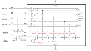
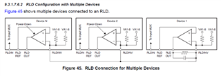
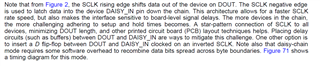
2. Connect two chips in a daisy-chain configuration. Do the SRB1 pins on both chips need to be connected together? Refer to the diagram for problem 1 for the channel connection between the two chips.

3.If the bias bias drive is shared by both chips using the first chip's bias output, does the second chip's biasout and biasin pins not need to be connected, and only the biasin pin of the second chip needs to be connected to the biasin pin of the first chip?

I would appreciate your reply!

Thank you!

  • Hello Jiahao,

    Thank you for your post.

    1. Unused analog input pins should be tied to AVDD.
    2. Yes, if the INxP input signals of both chips are measured against the same reference electrode, it would make sense to short the two SRB1 pins together. 
    3. Only the BIASOUT of one device is needed (i.e. Device 1). The BIAS amplifier of the other devices (Device 2, 3, ...) can be powered down. It is still possible to select input electrodes from any device and connect them to the BIASINV pin of Device 1 to include them in the common-mode derivation circuit, if desired. An example of this is shown in our ADS1298 data sheet and would apply to the ADS1299 as well:

    Regards,

    Ryan

  • Hello Ryan

    Thank you so much for your reply.

    1. How can the BIAS amplifier of other chips be powered down, please? I have learned that in the daisy-chain mode, the configuration is consistent.

    2、As shown in the figure below, if only two chips are connected in a daisy chain with a distance of about 50mm between DOUT and DAISY_IN, do you also need to add delay circuits or D flip-flops?

    thank you!

  • If a delay circuit needs to be added in question 2, how long is the delay time required?

  • Hi Jiahao,

    1. You make a good point. If you are using a common /CS for both devices in the daisy-chain, they must have the same register configuration. It is possible to use separate /CS for each device during register writes, and bring them low at the same time during data collection.

    2. The need for a delay circuit or D flip-flop circuit to re-clock the data will depend on the layout and SCLK frequency in your system. I have not heard of any customers actually requiring this circuit in the past since the SCLK frequency is relatively low.

    The setup time from SCLK rising edge to DOUT is 17 ns / 32 ns (depending on DVDD). So 1/2*SCLK period must be longer than the setup time with some margin to ensure that the bit is settled on the DAISY_IN pin before the next SCLK falling edge. I would think SCLK < 10 MHz should not have any issues (50 ns high and low time for SCLK).

    Regards,

    Ryan

  • Hello Ryan

    Thank you so much for your reply.

    Can I understand that as long as SCLK is < 10MHz, there is no need to add delay circuits or Dflip-flops?

    thank you!

  • Hi Jiahao,

    You will need to check the timing and verify there is enough margin. There is no such "rule" that delay circuits or D flip-flops are not required if SCLK < 10 MHz. My estimation is that it will not be necessary, but it is up to you to confirm.

    Regards,

    Ryan