- Ask a related questionWhat is a related question?A related question is a question created from another question. When the related question is created, it will be automatically linked to the original question.
This thread has been locked.
If you have a related question, please click the "Ask a related question" button in the top right corner. The newly created question will be automatically linked to this question.
Tool/software:
Hi,
I have a TLV2548IPW and I am currently trying to get it working. However, whatever I do , I do not get any sensible results. Is there a source code for this family that I can refer to and see if I am doing something wrong ?
Any help will be appreciated very much. Thank you.
Hi Midhun,
Unfortunately, this being an older device that has since been superseded, there isn't any available example code for it. If you are able to share logic captures of the communications you are currently attempting to send, I could help you in debugging them. Is there a specific you would like to accomplish with this device, such as reading conversion from a certain sequence of channels?
Regards,
Joel
Unfortunately, nothing I am doing seems to be working. So anything that points me in the right direction will be a great help. For starters, I am trying to write a configuration to CFR and read from it. That would be a nice first step.
Hi Midhun,
I am not sure how far you are into your design. However, we would recommend that you move to the ADS7038, as newer and better alternative. We do have example code for the ADS7038; found on our GitHub page - https://github.com/TexasInstruments/precision-adc-examples/tree/main/devices/ads7038.
-Kyle
Hi Kyle, it is a bit too late for us to go back and switch to another ADC. Is there any other way you could help us with our issue ? We tried using the Aardvark host adapter to see the ADC in action but the response of the ADC to basic command like write to CFR or read from CFR did not make sense. Sometimes the response were as expected but most of the times it did not make much sense. I'd appreciate any help in making this work.
Hi Midhun,
My description below will assume that you are utilizing just 4 lines for the SPI interface (~CS, SCLK, SDI, and SDO). If you are using other available communication pins, please let me know. I'm also assuming one shot mode (mode 00) as a starting point. I recommend beginning this sequence after fully power cycling the device.
First, I'd like to see if you can read the contents of the CFR register. Since we're focusing just on the SPI pins, ~CSTART and ~FS should be tied to Vcc.
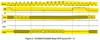
Each SPI frame is 16-bits long, i.e. 16 SCLK cycles long, and begins with a falling edge from ~CS, and ends with a rising edge of ~CS. Note that the TLV2548 samples SDI on rising edges of SCLK, and the MCU should sample SDO on rising edges of SCLK as well.
The MCU should send 1001b as the first 4 bits on SDI. The remaining 12 bits are don't cares.
In the same cycle, the device should respond with the contents of the CFR register on OD11-OD0, corresponding to the rising edges of SCLK cycle, 5 through 16.
I've highlighted the lines we should be monitoring in the image below. We don't care about the rest since they should be static throughout the cycle. Just quickly confirm the levels of these pins with a multimeter. Can you share a logic capture of the 4 highlighted pins with the sequence as described above? This will help verify what the CFR is set to, and whether there isn't any other issue with the specific device you are using. Please also confirm what SCLK frequency you are using.

Regards,
Joel