


Tool/software:
Dear Expect:
Current problems:
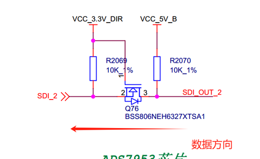
1. There are two AD conversion chips on the board, one of which has four pins of GPIO0~GPIO3 suspended in the air and can read data normally, but there is a small induction waveform of SDO OUT
2 on the port of GPIO0 seen from the oscilloscope; However, GPIO0~GPIO3 is suspended in the air in the other piece, and data cannot be read normally. Only by short-circuited GPIO0 and SDO OUT2 can GPIO0 be connected. 2. Key question: A. Does the four GPIOs have input requirements? B. Has the GPIO port been configured as an input port in the current software configuration? What is the definition or requirement of the input port?


Configure the ADS7953-Q1 in AUTO-2 mode:
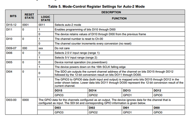
he mode is 0X3C40. According to my understanding, after this configuration, four GPIO ports should be set as INPUT, but I don't see what the input high or low level means, and it is somewhat similar to the suspended input at present. When the software is initialized, 0x3c40 is configured, and the cyclic collection of values begins.


