This thread has been locked.

If you have a related question, please click the "Ask a related question" button in the top right corner. The newly created question will be automatically linked to this question.

ADS42LB69: ADS42LB69 strange level behaviour

Part Number: ADS42LB69

Tool/software:

Hi,

We are using the ADS42LB69 to acquire a 250 MHz sinusoidal signal. I then demodulate the signal to obtain the IQ components using the direct sampling technique, where I sample the signal at 133.333 MHz, which corresponds to (8/16) * 250 MHz.

The issue is that the digital samples exhibit unusual noise, but not at all digital steps (see figure).

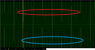
In the red circle, you can observe that the digital samples have greater dispersion compared to those in the blue circle.

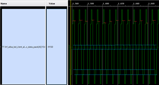
Upon zooming in, you can clearly see the dispersion across the different digital steps.

When I analyze this using Octave, I get the following results:

It doesn’t appear to be glitches in the capture; rather, it seems like a level jump.

I would like to know if this could be an issue with the ADC and its configuration, or if it might originate from the 250 MHz input RF signal.

We have successfully used this ADC in previous projects. One of the main differences in this project is that we perform downconversion from 1.5 GHz to 250 MHz using a mixer before sending the signal to the ADC

Any suggestions would be greatly appreciated.

Thanks and best regards,

Juan. 

  • Hi Juan,

    Please send over your schematics and the way you are testing your board, that might help us find the issue?

    Have you tried an ADC ramp/test pattern to see if there are any discontinuities?

    Regards,

    Rob

  • Hi Rob, 

    Thank you for your response. I’ve generated the ramp patterns, and they look perfect. Regarding the schematics, our architecture has been performing well with an RF input signal at 176 MHz and an ADC sampling frequency of (8/9) * 176 MHz = 156.444 MHz. The main difference in this setup is the use of a mixer to downconvert the 1500 MHz RF input signal to 250 MHz before it is sampled by the ADCs.

    My main question is whether this issue could be caused by a malfunction in the ADC or if it is more likely to be related to noise and coupling effects due to the downconversion architecture (mixer, LO generation, amplifiers...).

    Regards,

    Juan.

  • Hi Juan,

    The mixer or anything new added into the signal chain could be the culprit.

    Can you turn off the LO to the mixer and bypass the mixer totally?

    Then apply a signal directly into the ADC and check your output results again.

    This will tell you if the mixer is the issue.

    Regards,

    Rob

  • Hi again, 

    Thanks for your response. After some testing, it seems that this ADC lane is broken. We tried another board (same design) and it works. We are in a redesign phase and we manipulated the board so the ADC was probably damaged in the process.

    Thanks and regards,

    Juan.