This thread has been locked.

If you have a related question, please click the "Ask a related question" button in the top right corner. The newly created question will be automatically linked to this question.

ADS42LB69: Function of TEST PAT ALIGN field in register 8

Part Number: ADS42LB69


Tool/software:

Hello, 

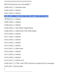
Can someone please help me understand about the TEST PAT ALIGN field in register 8 of ADS42LB69?

As I understand it, writing 1 to the TEST PAT ALIGN field will synchronize the phase of the test pattern of channel A and channel B, so for example, if I select digital ramp as the test pattern, the same data will be output from the two channels.

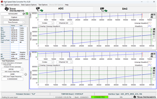
Unfortunately, the output data sequences are not actually in phase. I have confirmed that each channel is digital ramping independently.

Am I understanding something wrong?

Best Regards,

Keisuke

  • Hi Keisuke,

    How is this test being setup?

    Are you using the ADC EVM or your own board design?

    Regards,

    Rob

  • Hi Rob,

    Thank you for your reply. As you pointed out, we did not include important information.

    Basic information is as follows:

    - My own board design

    - CLKIN : 240 MHz

    - Clock source: FPGA

    - DDR format

    - Test pattern Ch A/B: Digital ramp (0100)

    - Clock divider bypassed

    - FPGA: Xilinx Zynq-7000

    When the test pattern from the ADC was captured into the FPGA, the phases of the count-up patterns for channels A/B were not aligned. I looked at the datasheet and found a register for synchronizing the test patterns for each channel, so I tried using it, but no change appeared.

    Best Regards,

    Keisuke

  • Hi Keisuke,

    Please send me the complete register listing that is being programmed into the ADC.

    That would help too.

    Thanks,

    Rob

  • Hi Rob,

    Thanks for your support. The register list is as follows, in C source, address/value pairs.

    //////////////////////////////////////////////////////////

    ADCCommand adc_init_command[] = {

    { 0x08, 0x01 }, // Sotfware reset

    { 0x06, 0x80 }, // Default

    { 0x07, 0x00 }, // Default

    { 0x08, 0x0C }, // Default DIS CTRL PINS enable, TEST PAT ALIGN

    { 0x0B, 0x00 }, // Default

    { 0x0C, 0x00 }, // Default

    { 0x0D, 0x6c }, // Default

    { 0x0F, 0x44 }, // Test Pattern Digital Ramp

    { 0x08, 0x0C }, // Default DIS CTRL PINS enable

    { 0x10, 0x00 }, // Default

    { 0x11, 0x00 }, // Default

    { 0x12, 0x00 }, // Default

    { 0x13, 0x00 }, // Default

    { 0x14, 0x00 }, // Default

    { 0x15, 0x01 }, // DDR mode

    { 0x16, 0x00 }, // Default

    { 0x17, 0x00 }, // Default

    { 0x18, 0x00 }, // Default

    { 0x1F, 0x7F }, // OVR th 0x7F

    { 0x20, 0x01 }, // CTRL1 and CTRL2 function as output pins for overrange.

    { 0xff, 0xff } // dummy data

    };

    //////////////////////////////////////////////////////////

    Best Regards,

    Keisuke

  • Hi Keisuke,

    Please give me a few days to set this up in the lab and verify.

    Thanks,

    Rob

  • Hi Keisuke,

    I was able to get this to work.

    Please delete this line highlighted below.

    Here is a snapshot of the ramp patterns in phase:

    Thanks,

    Rob

  • Hello Rob,

    Thanks for spending your time for me. I have “almost” aligned the pattern using the way you described. Almost is the important part, technically it was still eight clocks misaligned. (I am trying to upload a screenshot, but for some reason it doesn't seem to upload properly. Sorry.)

    I would like to ask a few questions.

    Question 1: Is the pattern alignment being off by 8 clocks a reasonable behavior for this ADC's specifications? Or am I still missing something? Does the alignment of the two channels in your lab match perfectly with clock accuracy?

    Question 2: Can you explain why it works if I remove the command to the ADC? After enabling the test pattern, will alignment be taken on the rising edge of the TEST PAT ALIGN bit?

    Our project is actively trying to use this ADC for future development. Therefore, I am asking the above questions to learn more about the characteristics of the ADC.

    Best Regards,

    Keisuke

  • Hi Keisuke,

    Are you using the same spi register sequence you gave to me? Minus the line I highlighted above? If so, you should have no issues aligning the data between the two ADC within the same device.

    The register sequence matters in this case for this specific ADC.

    Regards,

    Rob