This thread has been locked.

If you have a related question, please click the "Ask a related question" button in the top right corner. The newly created question will be automatically linked to this question.

AMC131M01: Issue with DCDC Output When Controlled via SPI

Part Number: AMC131M01
Other Parts Discussed in Thread: AMC131M03,

Tool/software:

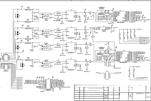
I am using an STM microcontroller to control the AMC131M01DFMR using SPI. I have enabled the DCDC bit, and the CIN frequency and divider are set to default. A continuous clock is provided at CIN after power-up. After that, write register and read register commands are sent for configuration, with only the DCDC bit enabled while keeping everything else at default. However, I am not getting any voltage at the DCDC output. What could be the possible reasons for this issue?

  • Hi Omkar,

    What is the application?

    Can you provide the following info on your system:

    1. What is the CLKIN frequency you are using
    2. Can you share the schematic
    3. Do you have captures of the digital communication

    Thanks.

  • The CLKIN frequency is 4MHz. I am attaching schematic for your reference.  

  • Hi Omkar,

    The DCDC_Freq register has to be set according to the CLKIN frequency before enabling the DCDC_EN.  The DCDC won't turn on properly unless the frequency setting is correct.

    Thanks.

  •  AMC131M03_WriteRead(0x04, 0x31,AMCDataTx, AMCData);

    if(counter < 1)
    {
    AMC131M03_WriteRead(0x03, 0x31,AMCDataTx, AMCData);
    AMCDataTx[0] = 0x01;
    AMCDataTx[1] = 0x0D;
    AMCDataTx[2] = 0x00;
    AMC131M03_WriteRead(0x01, 0x03,AMCDataTx, AMCData);
    HAL_Delay(1);
    AMCDataTx[0] = 0x0A;
    AMCDataTx[1] = 0x00;
    AMCDataTx[2] = 0x00;
    AMC131M03_WriteRead(0x01, 0x31,AMCDataTx, AMCData);
    HAL_Delay(1);
    AMCDataTx[0] = 0x0A;
    AMCDataTx[1] = 0x01;
    AMCDataTx[2] = 0x00;
    AMC131M03_WriteRead(0x01, 0x31,AMCDataTx, AMCData);
    HAL_Delay(1);
    counter++;
    if(counter == 1)
    HAL_GPIO_WritePin(GPIOB, GPIO_PIN_8, GPIO_PIN_SET);
    HAL_Delay(1);

    }
    else

    uint8_t AMC131M03_WriteRead(uint8_t command, uint8_t reg,uint8_t *txData, uint8_t *rxData) {
    uint8_t txFrame[9] = {0}; // 10 16-bit chunks = 5 words of 24 bits
    uint8_t rxFrame[9] = {0}; // Same size for receiving response

    // Prepare the command word
    uint16_t cmdWord = 0;

    if (command == 1) { // Write command
    cmdWord = (0x6000) | ((reg & 0x3F) << 7);
    } else if (command == 0) { // Read command
    cmdWord = (0xA000) | ((reg & 0x3F) << 7);
    } else if (command == 3) { // Read command
    cmdWord = 0x0000 ;
    }
    else if (command == 4) { // Read command
    cmdWord = 0x11 ;
    }else {
    return 1; // Invalid command
    }

    // Fill the transmit frame
    txFrame[0] = (cmdWord >> 8) & 0xFF; // Command high byte
    txFrame[1] = cmdWord & 0xFF; // Command low byte

    if(command == 1)
    {
    for(int i =0; i < 3; i++)
    {
    txFrame[i + 3] = txData[i];
    }
    }
    // // Construct the input frame (DIN in 16-bit chunks)
    // txFrame[0] = 0xB8;//((command << 8) | reg); // Command (8 bits) + Register (8 bits)
    // txFrame[1] = 0x80; // Padding or CRC (if CRC is disabled)
    // txFrame[2] = 0x0000; // Zero for 2nd word (high 16 bits)
    // txFrame[3] = 0x0000; // Zero for 2nd word (low 8 bits padded)
    // txFrame[4] = 0x0000; // Zero for 3rd word (high 16 bits)
    // txFrame[5] = 0x0000; // Zero for 3rd word (low 8 bits padded)
    // txFrame[6] = 0x0000; // Zero for 4th word (high 16 bits)
    // txFrame[7] = 0x0000; // Zero for 4th word (low 8 bits padded)
    // txFrame[8] = 0x0000; // Zero for 5th word (high 16 bits)
    // txFrame[9] = 0x0000; // Zero for 5th word (low 8 bits padded)

    // Transaction 1: Send command frame, ignore response
    AMC131M01_CS_LOW();
    HAL_SPI_Transmit(&hspi3, (uint8_t *)txFrame, 9, HAL_MAX_DELAY);
    AMC131M01_CS_HIGH();

    // Wait for response readiness (device-dependent delay, adjust as needed)
    // HAL_Delay(1); // 1 ms delay as an example; adjust per device timing

    // Transaction 2: Send dummy frame and receive response
    uint16_t dummyFrame[9] = {0}; // Dummy frame to clock out response
    AMC131M01_CS_LOW();
    HAL_SPI_TransmitReceive(&hspi3, (uint8_t *)txFrame, (uint8_t *)rxFrame, 9, HAL_MAX_DELAY);
    AMC131M01_CS_HIGH();

    // Reconstruct the response frame into 5 words of 24 bits each
    for (int i = 0; i < 5; i++) {
    rxData[i] = rxFrame[i];
    }

    return 0; // Success
    }

    I am setting commands to set the frequency. I am sending these commands. 

  • Hi Omkar,

    The DCDC_Freq selection in Table 8-31 is actually incorrect.  It's from a previous revision that was missed when updating the datasheet.  Please refer to Table 8-3, the one I responded with above, for the DCDC frequency setting.  Hopefully that fixes the issue.

    Thanks.

  • Thank You for your response.
    After changing the frequency also the issue is not resolved. I think there is some issue between communication as the response which I am observing is not as expected. I will explain the code which was posted above with the SPI settings and digital response which I got so it will be easy to trace the problem. I am including response of just 24 bits as that is my word size the response is stable so the SPI initialization seems correct I think the problem is with frames which are being sent.

    The SPI is running at 781.25KHz as MSB first. The settings of clock are polarity low and phase 2nd Edge. 
    The command sequence is ass follows:

    After power up:

    1. Read Status Register.

    Command = 0x000000000000000000  Response = 0x048000

    2. CLOCK Register all PWR = low power everything else default 

    Command = 0x618000010D00000000 Response = 0x410600

    3. DCDC_CTRL Register DCDC_FREQ = = 1.95 MHz to 2.12 MHz

    Command = 0x788000080000000000 Response = 0x59FC00

    4. DCDC_CTRL Register DCDC_EN = Enable

    Command = 0x788000080100000000 Response = 0x59FC00

    5. Read Status Register.

    Command = 0x000000000000000000  Response = 0x004000

    I don't know why but after these commands no matter what command I send the response remains same as 0x004000

  • Hi Omkar,

    It looks like the responses to your writes don't match up.  Can you scope out the SPI signals to verify the data sent?

    Thanks.