Tool/software:
Hello!
I have created a circuit board which uses the ADS127L0 in the following circuit:

Note that I have previously had an issue with this circuit because I missed the connection from pin6 to VCC and from pin28 to VCC to keep it enabled. I have fixed this manually but it is not reflected in the schematic.
As far as specifics go, note that the chip shares a common VCC and GND for the AVDD/DVDD and AGND/DGND. The filter and OSR pins are set in a way that it is running in low latency/2048x oversampling. This is because when i have a different filter and osr setting, the problem i am about to describe becomes worse.
Basically, when i plot the data from the ADC, i get occasional spikes when it should be a constant:
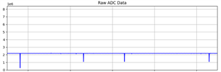
Note that I am plotting the raw value from the ADC here.
another example: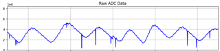
I have ensured that I am in the correct SPI mode, and am waiting for the DRDY pin to go low before polling for the data. This problem gets significantly worse (more spikes per 100 samples) for a lower OSR or a different filter, or if i decrease the delay in my main loop in code.
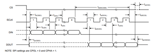
Due to this, it makes me believe it is a timing related issue, but per the datasheet i am using an spi clock of 2MHz which falls well within the range of acceptable values for a 3V power supply, and i am using the correct SPI mode. I am waiting for DRDY to go low before making a measurement, and i am delaying my loop by 1ms.
Is this likely to be a timing issue? If so, how can i fix it? or have i somehow damaged my ADC while soldering (note I have two which exhibit the same behavior)
Thanks!