Tool/software:
Hello,
1) can you help to review the schematic?
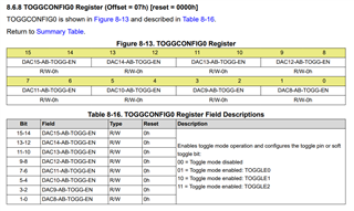
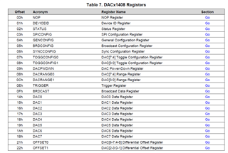
2) toggle mode register A and register B, where is it? It's not in register map.
3) toggle pin, only 3 pin, does it mean we can pick up 3 of 8 channel use it?
4) toggle function, can I use 1k clock connect to toggle pin to generate PWM?