Because of the holidays, TI E2E™ design support forum responses will be delayed from Dec. 25 through Jan. 2. Thank you for your patience.

This thread has been locked.

If you have a related question, please click the "Ask a related question" button in the top right corner. The newly created question will be automatically linked to this question.

DAC5571 Address Question

Other Parts Discussed in Thread: DAC5571, DRV8825

Hello Tom,

it seems this thread is the only one about DAC5571, so I would like to join with one more question.

According to datasheet, the address of DAC is set at power-up by reading the A0 line. The datasheet also says that you can set the DAC in three power-down modes.

We will use two DAC5571 in a new board, having the A0 lines connected each to a separate output from the MCU. This way, we would like to decide at runtime which DAC is DAC0 and which DAC1.

Here is my question. Is it possible to change the I2C address with this sequence?

- power up the board.

- when the MCU is ready, set the A0 lines for the two DACs

- power down both DACs with a broadcast command

- restore normal operation. I expect that the state of A0 line is acquired, but datasheet is not clear on this point.

Kind regards

Giuseppe

  • Hi Giuseppe,

    The DAC5571 latches its address on the initial power up of the actual Vdd rail, but I see the text you are referring to regarding the ability to drive the A0 pin with TTL/CMOS logic levels.  That implies your scheme mentioned above might work and I agree that the data sheet is not clear on this point.  Let us investigate this a little and we'll get back to you ASAP.

  • Very good :-)

    We will close the project in the next few days, so it would be great to get an answer from TI (and I really hope the address can be changed at "runtime").

    Giuseppe

  • Hi Giuseppe,

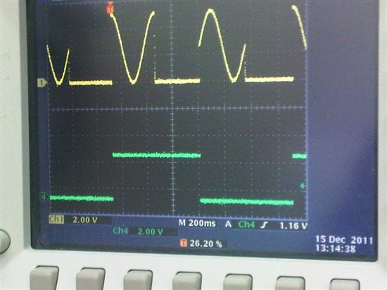
    We powered up the DACx571 board here and toggled the address bits on the fly. We found that you are able to change the address pins on the fly. The initial state latched into the device on power up is not fixed until the next power up. Looks like your setup will be ok.

    Regards,

    Tony Calabria

  • Hi Guiseppe,

    Here is a screen shot from our results. Channel 1 is the analog output and channel 4 is the status of the A0 pin. The code was designed to set the address bit low, output one period of a sine wave, followed by the power down command. Then, change the address byte to bring it high, write one period of a cosine (using the new address in the I2C write byte), and write the power down command again. This sequence would repeat.

    Regards,

    Tony and Tom (Tom took the pictures and wrote the uC code)

  • Hi Tony and Tom :-)

    I am really in a hurry, the board is still not ready, but this information allows me to prepare the code in advance and gain some time.

    Thanks for the support

    Giuseppe

  • One last thing.

    This feature of 5571 also allows overcoming the limitation of two DACs per board.

    You need to connect the A0 line of each DAC to a different I/O of your MCU, then you can perform the sequence:

    - power down all DACs with a broadcast call

    - set all A0 lines to 0 except that of DAC you need to write

    - power up the DAC with address 0x9a

    - write the value

    - repeat for other DACs

    This method is neither straightforward nor fast, but allows you to have as many DAC5571 as your I/O lines :-)


  • Hi Giuseppe,

    What exactly is your application here?  Tony and I were both scratching our heads asking 'Why?' you might want to do this.  I suppose you are correct in that you could add additional DACs up to the limit of your GPIO, but you could really only control two parts at any one time without re-configuring (ignoring general call/broadcast modes).  So...what are your building?  I'm intrigued...

  • Hi,

    We started developing a two-axes control board with two DRV8825. The DACd are used to limit the maximum current to each axis. We selected 5571 because is small, cheap and easy to use.

    When the project was already completed, our customer asked:  "what if I need two more axes in the future?". So we designed a pluggable daughterboard, and quickly faced the problem of the DAC address.

    At that point, we didn't want to change the main board. We didn't want to have a different DACs in the daughterboard, either.

    So we studied the datasheet of 5571 and found this "escape strategy" that could work.

    In short: if the four-axes requirement was clear from the beginning, probably we would have chosen a different component. But I suppose that "clear requirements" is like Sci-Fi...

  • Necessity is the mother of invention...  Thanks for the info!  Let us know if there is anything else we can help with.