This thread has been locked.

If you have a related question, please click the "Ask a related question" button in the top right corner. The newly created question will be automatically linked to this question.

DAC161S997: Self power configuration in DAC161S997

Part Number: DAC161S997

Tool/software:

Hello there,

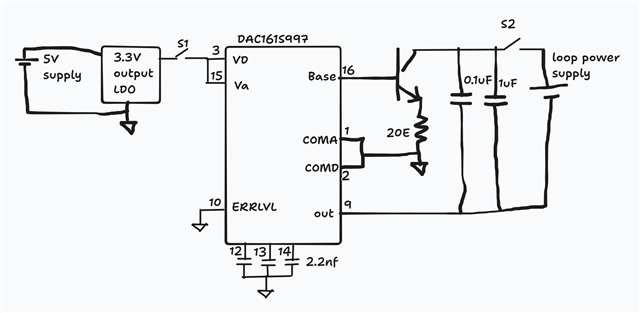
I am curious about self power configuration in DAC161S997 IC,

in the below self power configuration if S2 is ON and S1 is OFF does it harm DAC IC?
I believe if S1 is ON and S2 is OFF there will not be any issue.

also note that Loop power supply and 5V power supply are isolated from each other.

  • Pinal,

    Generally, I think the DAC161S997 is designed for loop-powered applications. However, if the VD and VA are powered from a separate supply, I don't think this would cause damage to the device, and you should be able to communicate with the device. Note that with S2 closed, the loop supply and the 5V supply have grounds that are offset by a voltage of the loop current times 40Ω.

    However, if you remove the loop connection by opening S2, you lose control of the loop. I'm not sure how this affects the entire circuit. I think the BASE pin pulls up on the base of the NPN to set the current which no longer can be set. The IDAC tries to source current, but with OUT connected to the ground of an isolated supply, I don't think the current wouldn't flow that direction.

    Out of curiosity, is there a reason you wanted to use a separate isolated 5V supply to power the DAC161S997?


    Joseph Wu

  • Thanks for the detailed response, Joseph.

    You're right — the primary reason for using a separate isolated 5V supply is to enable the use of low-cost opto-isolators for SPI communication and error signaling (ERRB, ERRLVL). 

    Also, I appreciate your explanation of what might happen when S2 is open and S1 is closed. That insight draws my attention towards the DAC’s operating behaviour, also please note that when i do so(S2 is open and S1 is Closed), i have seen that Supply current from LDO to DAC is significantly increased upto around 7mA. this also raises concerns about long term reliability.

    As per the datasheet (page 18), the self-powered configuration is described, but it leaves a few important operational questions unanswered. Based on the attached image from my original post, I’d like some help on the following field-use cases:

    1. S1 ON and S2 OFF: That is, the device is powered by the isolated 5V (via LDO), but the loop supply is disconnected.

      • This might occur in the field when the loop wiring is accidentally disconnected or during maintenance.

      • What are the implications for the DAC’s internal circuitry in this condition? Does the absence of loop current path ( or with OUT tied to isolated ground) create a risk of damage or instability?

    2. S1 OFF and S2 ON: That is, only the loop power is present while the 5V isolated supply is off.

      • If the user powers up the loop without ensuring the self-power supply is on, does this create a potential back-powering issue or undefined behavior for the DAC?

    Would greatly appreciate your thoughts on these two real-world corner cases.

    Thanks again!


    Pinal

  • Pinal,


    I'm not sure if I have specific answers to these questions. However, let me comment on it, and we'll see if that helps.

    Case 1: With S1 ON and S2 OFF, the device is powered but the loop is open. It doesn't surprise me that the VD and VA supply pull extra current. I would guess that the device is trying to drive the loop. Because the loop is open, the device is trying even harder to pull the loop current. My guess this extra current is being pulled into VA. I don't think that this would damage the device but this isn't something I've looked at. I would note that designers often misconnected the devices and tie OUT to ground. This isn't exactly the same condition, but it does similarly remove the current control from the loop. In those cases, I haven't seen any damage from the device.

    Case 2. With S1 OFF and S2 ON, the device loses power, but the loop is still connected. In that case, I would guess that that the loop current disappears, with no way to pull up on BASE to have current flow. I don't think there's a way to back-power the device from the loop path. There is a ground connection, but I don't see a way to get power back to VA or VD to keep the device on. I don't think this would damage the device either.

    I did take a quick look at the DAC161S997EVM and I'm not sure there's an easy way to test this with that particular board. The LDO connection to VA/VD from loop power is direct, without a way to easily inject a supply there.


    Joseph Wu

  • Hi Joseph,

    while testing circuit on GPCB my DAC IC got damaged(due to unknown reasons, most likely due to bad soldering),
    now i think i have to make a proper PCB and then need to test with above scenarios.

    will update you with the results with proper PCB,
    meanwhile if anything comes up in your mind please let me know,
    thanks again.

  • Pinal,

    Ok, I'll close this thread for now. When you're ready, you can start another thread.

    Have a look at the DAC161S997EVM. It's not necessarily set up the way you want to run it, but you may be able to simply modify it in a way to get it to work for you.

    Joseph Wu