ADS1261EVM: EVM Connection

Part Number: ADS1261EVM
Other Parts Discussed in Thread: ADS1261

Tool/software:

Hello experts,

Currently my customer is reviewing our ADS1261EVM for their industrial robot project.

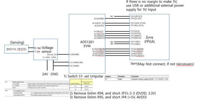
They are trying to connect AD1261EVM to voltage sensor, and voltage sensor's output is 5V. They are trying to do single-ended wiring.

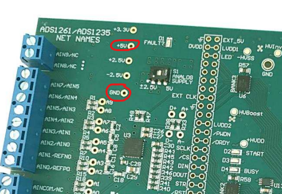
Could you please review below image if it would be ok for them to connect as below config for their lab test?

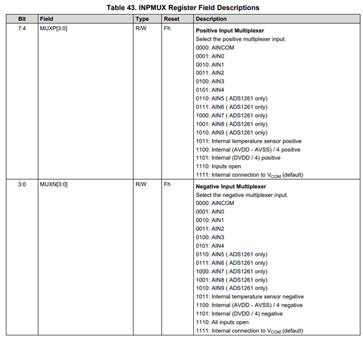
Also, AINCOM seems to be analog input common, but from datasheet it also seems that it is used like AD input as well. Would this be correct? That was why customer connected as below.

As customer is planning to go into lab for testing with below config today, your quick feedback would be very helpful.

Thank you in advance for your help and support.

  • Hi Jade Han,

    Can you please respond to my question in the Notes section of the Thread Tracking Toolkit?

    -Bryan

  • Hi Bryan,

    I added notes on the top of the page and clicked submit, and was not sure if it went through. Please let me know if you weren't able to get the message.

    Thank you.

    Best regards,
    Jade

  • Hi Jade Han

    Thanks for providing the requested information

    Does the customer want to bypass the controller on the EVM and communicate with the ADC using an FPGA? I don't see any connection for the DVDD voltage from the FPGA to the EVM for example

    The original question only asks about a single-ended voltage, but this request seems more complicated than that

    The input connections are correct for a 0-5V signal. As you said, AINCOM is just like any other analog input (it could be called "AIN10" instead). Make sure the customer disabled the PGA - otherwise they will not be able to measure single-ended signals

    -Bryan

  • Hi Bryan,

    Thank you so much for your feedback!

    My understanding is that they do want to bypass the controller on the EVM and communicate with the ADC using an FPGA, in that case, are there any connections they may have missed, and should be added?

    If above were not the case, other than DVDD voltage connection from the FPGA to the EVM, are there any other connections they should make? (I think for DVDD, they want to do external power supply because they wanted to connect JP3 2-3.

    Thank you for your help and support.

    Best regards,
    Jade

  • Hi Jade Han,

    The customer will have to

    • Install JP1 and install the shunt to hold the TIVA MCU in reset
    • Remove R94 and R95
    • Install JP3 and JP4, then jumper the center pins of each together (pin2 on JP3 to pin2 on JP4). Do not connect any shunts
    • Provide a clean +5V supply to the +5V net. This is pin 2 on JP3 or JP4
    • They also need to connect the FPGA ground to the EVM ground somewhere
    • Keep switch S1 in unipolar mode

    -Bryan

  • Hi Bryan,

    Thank you so much for your feedback!

    I had a few followup questions from customer,

    1. How can customer do PGA disable? I did not quite understand what PGA was..
    2. For single end input, could we understand AINCOM as ADC Inx's GND?

    Thank you for your help and support.

    Best regards,
    Jade

  • Hi Jade Han,

    The PGA (internal programmable gain amplifier) can be bypassed in the PGA register as shown in the first image below

    For single-ended measurements, the ADC is actually always measuring between two channels: MUXP and MUXN. See the second image below from the ADS1261 datasheet

    So the customer can apply their signal to any of the channels listed for MUXP, then ground any other channel listed in MUXN. The ADC will then measure the difference between MUXP and MUXN e.g. VIN = MUXP - MUXN. So no, the customer does not necessarily have to ground AINCOM, they can choose any channel including AINCOM

    -Bryan