ADS9817: Timing of sampling

Part Number: ADS9817
Other Parts Discussed in Thread: ADS9212, ADS9815, ADS9811, ADS9813

Tool/software:

Hi TI-Team

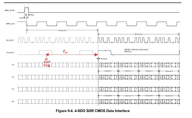
I am looking for the time tx between the sampling of the analog signals and the digital output of the sampled value of the ADS9817.
Currently, I am assuming that this time tx must be between 0 and t_{d_SYNC_FCLK}.
(The red X represents the moment when the analog signals of channels 1 and 8 are sampled)


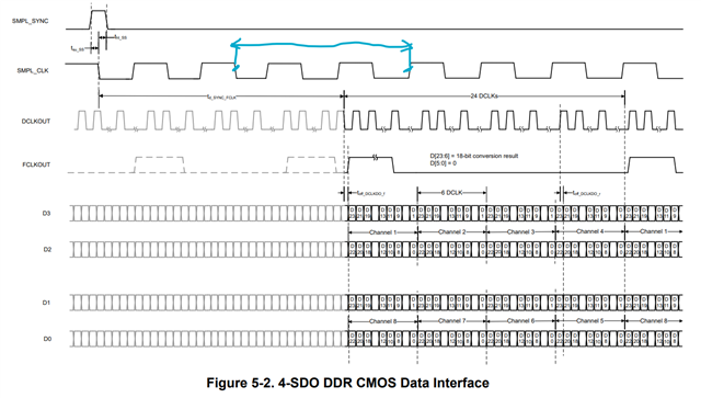
Regarding the timing between the channels: Is my assumption correct, that channel 2 is sampled 12 DCLK cycles after channel 1, and so on?

Kind Regards

  • Hi Andre, 

    Thanks for your post. May I ask what kind of application you are evaluating ADS9817 for? I'd like to share that we also have a simultaneous-sampling, pin-to-pin variant of ADS9817: ADS9813

    Your understanding is correct. I have marked below when CH1 is sampled and then when CH1 full data has been output from the ADC. CH2 is sampled 1 SMPL_CLK (12 DCLKs) cycle after CH1, and output accordingly.

    Best regards,

    Samiha

  • Thank you very much.
    The ADS9212 would have been the perfect fit for my application (two signals at a minimum of 1 MSPS and 18 bits with an LP filter and internal PGA).
    However, due to the limited availability of that ADC and similar ones, as well as the small quantity needed (no more than five), I decided to go with the ADS9817.

  • Hi Andre,

    Understood! The sim-sam devices in this family, such as ADS9813, have a feature (via register write) which converts the typically 8CH, 2MSPS/CH ADC into a 2CH 8MSPS/CH ADC, essentially mimicking ADS9212. The devices are pin-to-pin as well, so ADS9813 may serve as a replacement for ADS9212 if needed. There are also the ADS9811 (1MSPS/CH, sim-sam), and ADS9815 (1MSPS/CH, MUX) devices as well.

    Best regards,

    Samiha