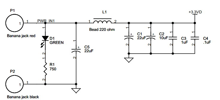
Hi, i am designing a pcb that mounts an ADS6422 and the power supply of the adc worries me slightly. The datasheet suggest powering the analog and digital supply pins from different supplies or isolate them using a ferrite bead. I have taken a look at the schematic of the evaluation board and have noticed that it uses both separate supplies and ferrite beads. I understand usually ferrites are placed to dissipate high frequency noise as heat, but i have simulated the combination of ferrite bead and decoupling capacitor and i cant make any sense of it. In my case i am going to employ two LDOs (with enough current to supply the adc) and was thinking of adding a little LC butterworth filter (fc=100 MHz and RL = 200 ohms) and placing 100nF decoupling capacitors near the suuply pins of the adc. Do you think this is okay? I wouldn't be adding any bulk capacitor (just 1uF at the input and output of the LDO) as the adc states little decoupling is needed, and besides the LDO is optimized for 1uF load. Opinions on this? What is the reasoning behind the combination of ferrite and bulk decoupling on the evaluation board?