Greetings,
Is there any information on the differential output drivers used in this device? My concern is that the output is settled before the ADC samples them.
Thank you,
Jim L.
This thread has been locked.
If you have a related question, please click the "Ask a related question" button in the top right corner. The newly created question will be automatically linked to this question.
Greetings,
Is there any information on the differential output drivers used in this device? My concern is that the output is settled before the ADC samples them.
Thank you,
Jim L.
Hi Jim.
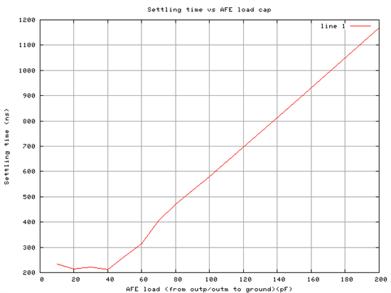
Please see the settling time for the output vs the load cap on OUTP and OUTM. Hope this helps.

Hi Surendranath,
Thank you for your response. I have a couple more questions. If the ADC I'm using is pipelined then you would like to have the output settle within a half cycle of the ADC clock frequency. Based on the graph it looks the fastest the ADC can run is about 1/(2*225ns)?
Would there be any decrease in settling time by following the AFE output with a differential amplifier?
Best Regards,
Jim L.
Hi Jim,
Yes, if you are not buffering the o/p, you will need to run your ADC at 1/(2*225ns) speed.
If you are buffering, the speed can be 1/(225ns). Essentially, the AFE0064 buffer will get full 225ns for settling and the added buffer gets 112ns => the added buffer needs to be designed for 112ns settling. Do note that the o/p of the AFE0064 can not be loaded with a resistor. So you can not use a diff in diff out amp with resistor feedback. You will need to put the amplifiers in buffer configuration (gain and common mode shift can be added as per the ADC requirements).
Can you tell me which ADC you are targeting and what is the intended application?
Regards,
Nagesh
Hi Nagesh,
I noticed that the specification has the following:
"OUTP or OUTM settling time to 16 bit accuracy with 15pf load and full scale step" 250ns (max)
Could you tell me the following:
"OUTP or OUTM settling time to 13 bit accuracy with 15pf load and full scale step" ??? (max)
Thank you,
Jim L.
Hi Jim.
If the load cap (15pF) is starting from output common mode (ie (refp+refm)/2), the setting time to 13bits is expected to be in the range 150n to 175ns. I wonder if this timing is ok for your needs.
I have a few questions to understand the scenario better
a) Is all of the 15pF the ADC sampling cap? Or, what is the split of static parasitic cap and switching load cap (ADC sampling cap). For a total of 15pF, the lesser the ADC sampling cap, the better will be the settling time.
b) Is there much difference in signal values expected from one channel to the next? If not, then (depending on the ADC architecture), the ADC cap needs little charge from one channel to the next.
c) Can you please tell me: What is the application (ie digital X-ray/photo-diode)? Which is the ADC targeted? What is the target speed?
Regards,
Nagesh
Hi Nagesh,
a) According to the ADC spec the sampling cap is 4pf and I'm guestimating (the PCB isn't complete yet) the parasitic's to be around 10pf.
b) Don't know about the difference is signal values between channels.
c) The application is a photo-diode array, and the AFE is configured in Simultaneous Mode where I was hoping to run it at the max frequency of 3.75MHz. The ADC is a LTC2245 due mainly to power savings.
Cheers,
Jim L.
Hi,
I will simulate for this case and let you know.
The ADC accepts +/-1V. Since the AFE gives out 1.4V signal, you will need to use the AFE charge compensation described in the datasheet of afe0064.
Is there an email I can contact you at?
Regards,
Nagesh
Hi,
With a 4pF switching capacitor of the ADC and a 10pF static parasitic cap, the output should settle within 133ns, which works for your target speed. Please note that these are numbers from simulations. We do not have a setup to measure the actual results. You may want to consider adding some margin.
Regards,
Nagesh