This thread has been locked.

If you have a related question, please click the "Ask a related question" button in the top right corner. The newly created question will be automatically linked to this question.

ADS8363 1MSPS

Other Parts Discussed in Thread: ADS8363, ADS8361, ADS8363EVM

Hello,

I have a TI 6416 DSK with 5-6k Card. I was using ADS8361 EVM (1 channel, 500KSPS) with the DSK and it was working fine. Now I am trying to increase my sampling using ADS8363 EVM. I have read the "ADS8361 Compatibility" section of the datasheet and made the following changes to my board.

Changes from ADS8361:

1. 2.5V external reference to TP4 and ground on TP3.

2. M1 = 0; M0 = 1

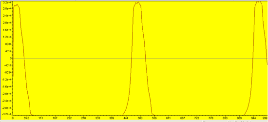
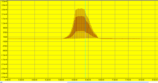
Signal is single sided and connected to A0+ (Pin 14) on the Analog side of EVM. When I connect A0- to ground I can get some signal and I have attached a graph to show the signal. The signal shape makes sense but it seems to go low every alternate sample.

Questions:

1. The alternate low samples are from channel B0? How can I avoid this without having to write to internal registers of ADC.

2. How can I get full scale range (0 -5v)?

3. Should I modify my code that was written for ADS8361? 

Thank you.


  • Hi Basavaraj,

    Basavaraj Hiremath said:
    1. The alternate low samples are from channel B0? How can I avoid this without having to write to internal registers of ADC.

    Since you have M1 = 0 SDOA and SDOB should be active. All of the data from the B converter will come out on SDOB. What you're seeing is the other differential pair on converter A. If you only want to see the first differential pair results on SDOA you could change your set-up to M1 = 0 & M0 = 0, which would put you in manual mode with data output on both SDOA and SDOB. If you didn't update any of the registers and stuck with all the default values by making dummy writes of all 0 on the SDI the part would default to converting the first differential pair on converter A and deliver those results on SDOA only.

    Basavaraj Hiremath said:
    2. How can I get full scale range (0 -5v)?

    If you're going to maintain not writing to any of the device's registers then you need to apply 2.5V on "A0-". Differentially then you could see a 0-5V range at the analog input, but resolving codes-voltages needs to be offset by 2.5V.

    Basavaraj Hiremath said:
    3. Should I modify my code that was written for ADS8361? 

    You should make any changes necessary to comply to the timing diagram of the ADS8363 - most of this is covered already in the Compatibility section you mentioned.

  • Hello Kevin,

    Thank you.

    Kevin Duke said:
    If you didn't update any of the registers and stuck with all the default values by making dummy writes of all 0 on the SDI the part would default to converting the first differential pair on converter A and deliver those results on SDOA only.

    This means I should write zeros or do not write anything since the default values are all zeros? 

    M1 = 0, M0 = 1; 

    Like you suggested, I connected the A0- to 2.5V. But I still had those alternate samples (again from A1 channel). If I connect the A1+ to the input signal and A1- to the 2.5V reference, I get a good signal (shown in figure below). But this is not correct... but one problem is solved... :) 

    If I make M0 and M1 zero, I get those alternate sample values again. 

    Best Regards,

    Basu 

  • Basavaraj,

    I spent some time in the lab today testing this. I took an ADS8363EVM with M1=M0=0 and grounded SDI. The first screen shot shows my results across CS/SDOA/CLK/RD.

    The highlighted areas in red are of note here. By default the ADS8363 outputs a channel ID bit, in this case consecutive reads are the same ID for differential pair A0.

    In this picture I applied a logical high on M0 while keeping M1 tied to ground. This sets the ADS8363 in automatic mode. Notice that this time the channel ID bits are changing.

    Basavaraj Hiremath said:
    This means I should write zeros or do not write anything since the default values are all zeros? 

    Since the interface is bi-directional you have to write to read. So you need to be writing all 0s - or just ground SDI.

    Basavaraj Hiremath said:
    Like you suggested, I connected the A0- to 2.5V. But I still had those alternate samples (again from A1 channel). If I connect the A1+ to the input signal and A1- to the 2.5V reference, I get a good signal (shown in figure below). But this is not correct... but one problem is solved... :) 

    Something else seems to be afoot here given the aforementioned results. Can you get a scope capture of your serial lines so we can review your timing?

  • Hello Kevin,

    Thank you. Connecting SDI to ground with M1 = M0 = 0 seem to work.

    Best Regards,

    Basu