This thread has been locked.
If you have a related question, please click the "Ask a related question" button in the top right corner. The newly created question will be automatically linked to this question.
Hi Gary,
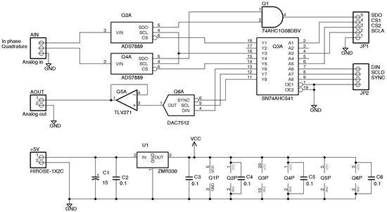
You are working too late on a Saturday I think! Can you provide a schematic and screen shots of your communication interface with the DAC7512? Your problem description does not necessarily indicate ESD damage, you may just have a simple communication setup issue. Let us know what controller you are working with as well (an MSP430, an FPGA, something else?).
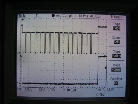
Below are the schematic and a screenshot of the sync and clock signals at the
dac inputs during an update. These signals at the input of the `541 switch
between 3.2 volts and ground. I found that there was some droop on VCC
during dac updates and I added a 10 uF cap across VCC and ground at the dac
chip. It appears that the dac is drawing a lot of current when sync is low
and hence has been damaged (the output is stuck at 2.4 volts). I installed
the chip a few days ago and was reasonably careful then and while testing
the board but, however, not wearing a ground strap. The adc portion of the
board works OK though I did have to add pull-ups on the inputs to the AND
gate.
The plan is to connect this board to an FPGA but for now for testing it is
connected to an MSP430 with a 4 MHz clock. The dac update code is shown
below. SYNC and SCL are initialized high.
static void dacNext(int dacVal)
{
int din, k;
din = dacVal;
P1OUT &= ~SYNC;
for (k = 0; k < 16; k++)
{
if (din & 0x8000)
P1OUT |= DIN;
else
P1OUT &= ~DIN;
P1OUT &= ~SCL;
P1OUT |= SCL;
din <<= 1;
}
P1OUT |= SYNC;
}
My apologies for the quality of the schematic image. I tried several times but could not improve it.
At the far right, it shows it goes up after the signal. Can you scope the DAC7512 pins 4 5 and 6 individually? The schematic shows pin 6 inverting, which it seems to, and the other 2 seem to be held high ( inverted output to low after the DAC7512 ). This would make me suspect both the DAC7512 and sn74ahc541 as possible culprits of a solid output rather than pulsed. Also if you can swap the connectors to Din, SCld Sync so that each has a turn on the 4 MHz clock to ensure the signal is getting out of the sn74ahc541.
Hope this brightens your Sunday,
Eric
Well it hasn't brightened my Sunday much but I appreciate you interest in my problem.
In the screen shot, the top trace is the clock signal and was that on pin 5 of the dac. The sync trace was probed at connector JP2 but I have verified that the signal at pin 6 of the dac is identical. The signal at pin 4 of the dac (DIN) is also identical to that at JP2. The code updates DIN about 100 usec before the falling edge of the clock; I don't think that has any bearing on this problem.
Gary, sorry to hear that.
The sn74ahc541 works at each side eliminating it as a suspect. That leaves any solder issues before calling the DAC as a burned component. I hate to admit how many times my solder work wasn't up to standard and caused an issue or one of my " new " breadboards being corroded causing lack of signal. The only thing left to test before calling it toast is to make * edited to correct * Din high, Sync tied to ground and tie clock to the input frequency and see if you get anything.
" Level triggered control input (active LOW). This is
the frame sychronization signal for the input data.
When SYNC goes LOW, it enables the input shift
register and data is transferred in on the falling
edges of the following clocks. The DAC is updated
following the 16th clock cycle unless SYNC is taken
HIGH before this edge, in which case the rising
edge of SYNC acts as an interrupt and the write
sequence is ignored by the DAC7512. "
Tomorrow is another day and an opportunity to make things better,
Eric