Because of the Thanksgiving holiday in the U.S., TI E2E™ design support forum responses may be delayed from November 25 through December 2. Thank you for your patience.

This thread has been locked.

If you have a related question, please click the "Ask a related question" button in the top right corner. The newly created question will be automatically linked to this question.

TLC3578

Other Parts Discussed in Thread: REF5040, TLC3578

Hi,

I am currently testing using the TLC3578IPW (TSSOP-24) on custom created board.

In this case i have pulled up the FS and CSTART as i dont have any dsp and all operations are to created using software

ref5040 is being used for 4v reference

i am testing this set up through a LPC1788 eval board

the spi clk is 100khz

in the current process i am sending 0xA000 then 0xAA03

then i am reading channel 5 which i have by default given 5V i am reading the same using 0x5000 but my output data is 0xFFFF

the INT and SDO line are always high when checked on the DSO for any operation

and i am not able to get any interrupt on the interrupt line

also i tried EOC mode but the INT is always high

is there any thing specific i am suppose to do which coding or any specific hardware changes.

Thanks Regards

Raquib Akolawala

  • Hi Raquib,

    I'm sorry to hear that you are having trouble with the TLC3578.  Could you post a schematic and possibly a screen capture showing the SDI/SDO, the /CS and the SCLK all together?  I'm sure we'll be able to get you up and running in no time with a little more detail on how you have your hardware configured.

  • Hi Tom,

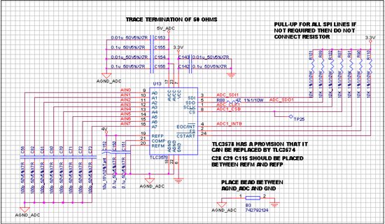
    I am attaching the adc image

    5V_adc is coming through a Pi-filter

    for 4V using ref5040 but today i removed.

    pulls ups are not connected for all, instead only r90 r110 i.e. FS CSTART

    Initially while testing CS vs SDO i would get SDO high during CS low period and the SDO would go low.

    Later I even stopped getting that.

    Currently my SDO pin remains low continuously, and int pin high.

    was following timing as per figure 11 pg28 of tlc3578 and CS CLK SDI were as mentioned.

    Verified the same on DSO.

    Also please let me if there any precautions I am suppose to take.

    Also how would i know if i have blown up my ic????

    I will get back with the DSO pictures.

    Thanks Regards

    Raquib Akolawala
  • Hi Tom

    I am attaching the images below

    Please note that yellow waveform is not proper because of error in probe but when i interchange it with the red one the wave is precise.

    please ignore the noise on yellow waveform.

    Yesterday I was configuring the TLC3578 in software mode bu sending 0xA000 but today i tried the same in hardware mode as i was getting reponse in the SDO line.

    Also the response of the same is in consistent

    the following waveform are on 100Khz clock frequency

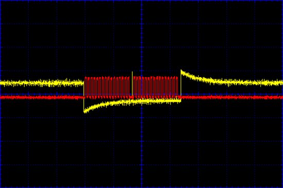
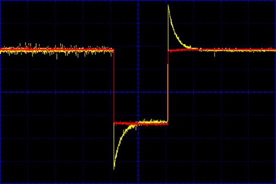
    Image 1.

    Y(ellow)-CS

    R(ed)-SCk

    after power on 2 consecutive cycles of chip select to select the hardware mode. At the same time my SDI is high.

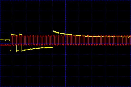
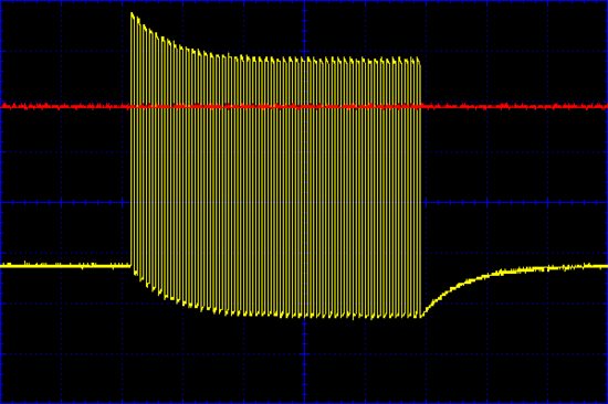
    Image 2

    Y-CS

    R-SCK

    Sending 0xD000 over SDI for select test for long sampling i.e. 48'CLK

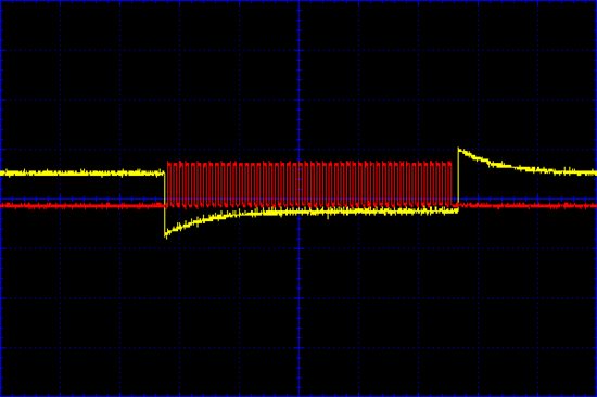
    Image 3.

    Y-SDI

    R-SCK

    0xD000 is being sent with respect ot the correspondig clock frequency.

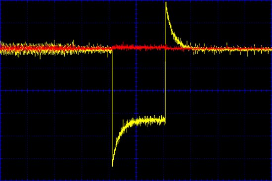
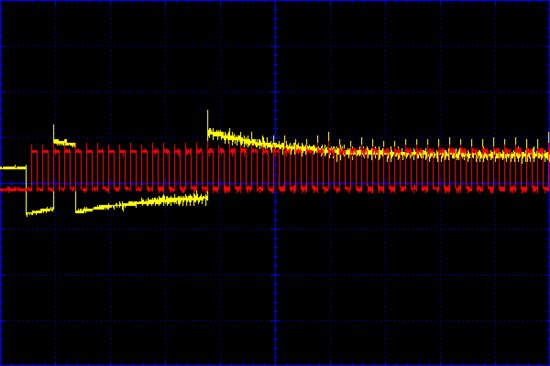
    Image4.

    Y-SDI

    R-SCK

    0X3000 to read from Ain3 on which I was applying 4V this voltage is not from ref5040 but from a seperate power supply

    also in the current setup i have not used ref5040.

    Image 5.

    Y-CS

    R-SDO

    Image 6.

    Y-CS

    R-SDO

    5 & 6 images are of CS and SDO lines which I have obtained please note in this case the SDO is either high or low throughout no change in any case

    I used this determine that my TLC3578 is working is this correct or please let me otherwise

    Also I connected a pull-up on this line today for testing purpose.

    Image 7.

    Y-SCK

    R-INT

    my interrupt line is high through out no matter what kind of instruction I give.

    Yesterday I posted the circuit diagram Please note that pull-up on cstart and fs are connected. today I connected the pull-up on SDO line.

    Also there is no Ref5040

    also i have put all the decoupling caps throughout

    Please let me know what is to be done as far as timing and hardware is connected.

    Also please let me know how to check if the IC is blown.

    Please can you help me with the same

    Thanks Regards

    Raquib Akolawala

  • What is causing the large over/under shoots on the yellow trace?  Try doing one of the test modes to see if you get the correct self test conversion results.

  • Hi Tom

    the overshoot and undershoot is because of error in probe

    also i tried the test mode with no results

    Also how do i test if the IC are working?????

    Thanks Regards

    Raquib Akolawala

  • Hi Raquib,

    I don't see anything 'wrong' with your hardware connections and the SCLK, SDO seem fine.  The only way to really check to see if the part is functional is to try and vary the EOC/INT setting and/or read out the test voltages.  Double check the soldering of the part and verify that the /CS, SCLK and SDO are actually reaching the pins of the TLC3578.

  • Hi Tom,

    The TLC3578 interrupts are being received on my custom board and the values are as per inputs.

    But there are still certain timing and interrupt issues I am facing

    1. I am receiving the updated output value of the input channel after 4th conversion cycles. For the same my adc is configured in 1-shot mode, and internal conversion clock

    2. When I check for the test voltage values even that I am getting after 4th conversion cycles.

    The commands I am sending are as follows in the sequence below.

    Send :0xA000

    Send: 0xAA03

    Send:0x4000 with delay(between sending the data) and receiving "Garbage"

    Send:0x4000 with delay(between sending the data) and receiving "Garbage"

    Send:0x4000 with delay(between sending the data) and receiving "Garbage"

    Send:0x4000 with delay(between sending the data) and receiving "Garbage"

    Send:0x4000 with delay(between sending the data) and receiving 0x8192 as the 4th channel is ground

    and then while reading the same channel i get the same value for unchanged input.

    When I change my input after this the process above repeats itself but instead of garbage I get previously held data and then after the 4th cycle i get the correct reading.

    I wanted to know if there are timing issues I am suppose to consider while reading and writing the data,

    the adc is working at 200KSPS and my SPI is working at 100Khz would this affect or cause change after 4th cycle.

    also is there any case in which the fifo can be affecting the output even though I am not actually setting the fifo.

    Also I have tried both the hardware mode and software mode and I am getting the same problem of 4 cycles

    Is there anything else you would require to know?

    Also please can you assist with the same.

    Thanks Regards

    Raquib Akolawala
  • Hi Raquib,

    Not sure where the problem may be here - use you O-Scope and try to confirm that the signal look like those depicted in Figure 11 on Page 28 of the data sheet.  The first SDO from power up will put 'garbage' out on the bus since there was no previously sampled/selected channel.  The sencod access should give you the conversion results from the first true t(SAMPLE) period.  How long is your delay?  If you are waiting many milliseconds, there is a possibility that you are bleeding off the sample/hold capacitor due to internal parasitics.

  • Hi Tom,

    I don't know how but my circuit miraculously started working on my custom PCB.

    I still haven't figured out the logical explanation for the same but will let you once i find it.

    Thanks Regards

    Raquib Akolawala