Hello ti,
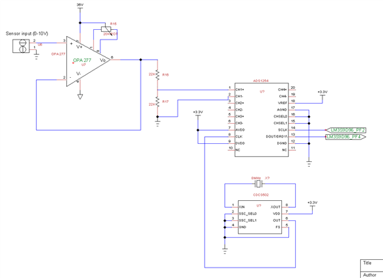
I am trying to interface ADS1254 to LM3s9d96.
I am having trouble in interfacing with the microcontroller SSI protocol. I have configured the SSI as below:
ROM_SSIEnable(SSI1_BASE);
SSIConfigSetExpClk(SSI1_BASE,SysCtlClockGet(), SSI_FRF_TI,SSI_MODE_MASTER, 20000, 15);
ROM_SysCtlPeripheralEnable(SYSCTL_PERIPH_SSI1);
and to read I'm using this function in a timer0 interrupt routine
ROM_SSIDataGet(SSI1_BASE,data_adc);
ADS1254 datasheet clearly specifies the timing routine to read ADC data. DOUT/DRDY\ pin goes low for time t2 and then will drive the line to high in time t1 indicating the data is ready to be read. Data will be shifted out on pin at time t7. If signal is high then the DOUT/DRDY\ will stay high for time t3. Device communicating with ADS1254 then can provide SCLK to ADS1254 after time t6. The communication is big endian type where msb will be transmitted first and then lsb.
LM3s9d96 has 16bit buffer, so just confused will it save the whole 24bit data? I have to make use of 8bit receive format and then divide. Well this is fine.
But i initialize the SSI only once. I don't know how to adjust this timings of SSI accordingly with the ADS1254 timings. I have read the sample programs which includes TI microcontroller MSP430F449. It is using UART in SPI mode which has the functionality to synchronize the ADS1254 device.
I am also facing problem at the SSI configuration function. If i do it. The whole code freezes. I cant see any change after that on run mode. My kit is (DK - LM3S9D96)
May be I'm doing something wrong. Please help me solving this problem. The code i programmed is below:
#include "inc/lm3s9d96.h"
#include "inc/hw_ints.h"
#include "inc/hw_memmap.h"
#include "inc/hw_types.h"
#include "driverlib/debug.h"
#include "driverlib/interrupt.h"
#include "driverlib/sysctl.h"
#include "driverlib/timer.h"
#include "driverlib/rom.h"
#include "grlib/grlib.h"
#include "drivers/kitronix320x240x16_ssd2119_8bit.h"
#include "drivers/set_pinout.h"
#include "drivers/thumbwheel.h"
#include "stdio.h"
#include "string.h"
#include "stdlib.h"
#include "inc/hw_ints.h"
#include "inc/hw_memmap.h"
#include "inc/hw_types.h"
#include "inc/hw_adc.h"
#include "driverlib/adc.h"
#include "driverlib/gpio.h"
#include "driverlib/interrupt.h"
#include "driverlib/sysctl.h"
#include "math.h"
#include "utils/ustdlib.h"
#include "inc/hw_types.h"
#include "driverlib/interrupt.h"
#include "grlib/grlib.h"
#include "grlib/widget.h"
#include "grlib/canvas.h"
#include "grlib/pushbutton.h"
#include "string.h"
#include "driverlib/rom.h"
#include "driverlib/ssi.h"
//#include "drivers/circle.h"
//*****************************************************************************
//
//! \addtogroup example_list
//! <h1>Timer (timers)</h1>
//!
//! This example application demonstrates the use of the timers to generate
//! periodic interrupts. One timer is set up to interrupt once per second and
//! the other to interrupt twice per second; each interrupt handler will toggle
//! its own indicator on the display.
//
//*****************************************************************************
//*****************************************************************************
//
// Flags that contain the current value of the interrupt indicator as displayed
// on the CSTN display.
//
//*****************************************************************************
//*****************************************************************************
//
// Graphics context used to show text on the CSTN display.
//
//*****************************************************************************
tContext g_sContext;
char stringx[100];
int adc_value;
unsigned long *data_adc;
//*****************************************************************************
//
// The error routine that is called if the driver library encounters an error.
//
//*****************************************************************************
#ifdef DEBUG
void
__error__(char *pcFilename, unsigned long ulLine)
{
}
#endif
//*****************************************************************************
//
// The interrupt handler for the first timer interrupt.
//
//*****************************************************************************
void
Timer0IntHandler(void)
{
// Clear the timer interrupt.
//
ROM_TimerIntClear(TIMER0_BASE, TIMER_TIMA_TIMEOUT);
// Update the interrupt status on the display.
//
ROM_IntMasterDisable();
ROM_IntMasterEnable();
}
//*****************************************************************************
//
// The interrupt handler for the second timer interrupt.
//
//*****************************************************************************
void
Timer1IntHandler(void)
{ ROM_TimerIntClear(TIMER1_BASE, TIMER_TIMA_TIMEOUT);
ROM_IntMasterDisable();
tRectangle sRect;
tRectangle yRect;
sRect.sXMin = 40;//lX1;
sRect.sYMin = 40;//lY1;
sRect.sXMax = 320;//lX2;
sRect.sYMax = 80;//lY2;
GrContextForegroundSet(&g_sContext, ClrWhite);
GrRectFill(&g_sContext, &sRect);
adc_value++;
ROM_SSIDataGet(SSI1_BASE,data_adc);
//print graph points on screen
GrContextForegroundSet(&g_sContext, ClrBlack);
sprintf(stringx,"%d",adc_value);
GrStringDraw(&g_sContext,stringx,-1, 40, 40,0);
yRect.sXMin = 80;//lX1;
yRect.sYMin = 80;//lY1;
yRect.sXMax = 320;//lX2;
yRect.sYMax = 80;//lY2;
GrContextForegroundSet(&g_sContext, ClrWhite);
GrRectFill(&g_sContext, &yRect);
GrContextForegroundSet(&g_sContext, ClrBlack);
sprintf(stringx,"%d",data_adc);
GrStringDraw(&g_sContext,stringx,-1, 80, 80,0);
ROM_IntMasterEnable();
}
//*****************************************************************************
//
// This example application demonstrates the use of the timers to generate
// periodic interrupts.
//
//*****************************************************************************
int
main(void)
{
volatile unsigned long ulLoop;
//
// Set the clocking to run directly from the crystal.
//
ROM_SysCtlClockSet(SYSCTL_SYSDIV_1 | SYSCTL_USE_OSC | SYSCTL_OSC_MAIN |
SYSCTL_XTAL_16MHZ);
//
// Set the device pinout appropriately for this board.
//
PinoutSet();
//
// Initialize the display driver.
//
Kitronix320x240x16_SSD2119Init();
//
// Initialize the graphics context and find the middle X coordinate.
//
GrContextInit(&g_sContext, &g_sKitronix320x240x16_SSD2119);
//
// Put the application name in the middle of the banner.
//
tRectangle sRect;
sRect.sXMin = 0;//lX1;
sRect.sYMin = 0;//lY1;
sRect.sXMax = 320;//lX2;
sRect.sYMax = 240;//lY2;
GrContextForegroundSet(&g_sContext, ClrWhite);
GrRectFill(&g_sContext, &sRect);
GrContextFontSet(&g_sContext, &g_sFontCm20);
GrContextForegroundSet(&g_sContext, ClrBlack);
GrStringDraw(&g_sContext,"adc test",-1, 10, 0,0);
ROM_GPIOPadConfigSet(GPIO_PORTF_BASE,GPIO_PIN_3,GPIO_STRENGTH_8MA,GPIO_PIN_TYPE_STD_WPU);
ROM_GPIOPadConfigSet(GPIO_PORTJ_BASE,GPIO_PIN_7,GPIO_STRENGTH_8MA,GPIO_PIN_TYPE_STD_WPU);
ROM_GPIODirModeSet (GPIO_PORTF_BASE, GPIO_PIN_3, GPIO_DIR_MODE_OUT);
ROM_GPIODirModeSet (GPIO_PORTJ_BASE, GPIO_PIN_7, GPIO_DIR_MODE_OUT);
ROM_GPIOPinTypeGPIOOutput(GPIO_PORTF_BASE, GPIO_PIN_3);
ROM_GPIOPinTypeGPIOOutput(GPIO_PORTJ_BASE, GPIO_PIN_7);
ROM_SysCtlPeripheralEnable(SYSCTL_PERIPH_SSI1);
ROM_SysCtlPeripheralEnable(SYSCTL_PERIPH_TIMER0);
ROM_SysCtlPeripheralEnable(SYSCTL_PERIPH_TIMER1);
//
// Configure the SSI.
//
ROM_SSIEnable(SSI1_BASE);
SSIConfigSetExpClk(SSI1_BASE,SysCtlClockGet(), SSI_FRF_TI,SSI_MODE_MASTER, 20000, 15);
//
// Enable the peripherals used by this example.
//
//
// Enable processor interrupts.
//
ROM_IntMasterEnable();
//
// Configure the two 32-bit periodic timers.
//
ROM_TimerConfigure(TIMER0_BASE, TIMER_CFG_32_BIT_PER);
ROM_TimerConfigure(TIMER1_BASE, TIMER_CFG_32_BIT_PER);
ROM_TimerLoadSet(TIMER0_BASE, TIMER_A, ROM_SysCtlClockGet()/20);
ROM_TimerLoadSet(TIMER1_BASE, TIMER_A, ROM_SysCtlClockGet()/20);
//
// Setup the interrupts for the timer timeouts.
//
ROM_IntEnable(INT_TIMER0A);
ROM_IntEnable(INT_TIMER1A);
ROM_TimerIntEnable(TIMER0_BASE, TIMER_TIMA_TIMEOUT);
ROM_TimerIntEnable(TIMER1_BASE, TIMER_TIMA_TIMEOUT);
//
// Enable the timers.
//
ROM_TimerEnable(TIMER0_BASE, TIMER_A);
ROM_TimerEnable(TIMER1_BASE, TIMER_A);
//
// Set pins 0 and 3 as output, SW controlled.
//
ROM_GPIOPinWrite(GPIO_PORTF_BASE,GPIO_PIN_3,0); //Setting Channel select as 0
ROM_GPIOPinWrite(GPIO_PORTJ_BASE,GPIO_PIN_7,0);
while(1)
{
}
}


