This thread has been locked.

If you have a related question, please click the "Ask a related question" button in the top right corner. The newly created question will be automatically linked to this question.

DAC8562 code example

Other Parts Discussed in Thread: DAC8562, DXP, ADCPRO, ADS1278

Hello,

I'd need a simple code (written in C) to control the DAC8562 EVM. Could anybody send me something in order to speed up the development? I've found the next statement in the EVM documentation but I'm not able to find anything and email support does not work.


Thanks in advance,
gaston

  • Hello Gaston,

    Thanks for your patience in your quest for support on this issue. I have not seen this question come through our list server, was your email rejected? If so you can you share the error message you got? This might be something that we need to look into and get resolved on our side.

    We have application notes about interfacing similar devices to the DAC8562 available but nothing directly for it. Those applications notes would be Interfacing the DAC8564 to the MSP430F449 and Interfacing the DAC8560 to the MSP430F449.

    If those do not suit your needs let me know and I could cook up some flow chart or pseudo code quickly to help you out or answer any specific questions you have about implementing this device.

  • Kevin,

    Thank you for your fast response.

    Kevin Duke said:
    If so you can you share the error message you got?

    Sure, here's the email response from ti:

    The message you sent to the mailing list dataconvapps,
    with the subject line:
    DAC8562 code example was not sent
    to the list subscribers because you do not have permission
    to send messages to this mailing list. If you did not send
    a message to the mailing list named above, be aware that
    the named list may be subscribed to a list to which you did
    send a message. In that case, only the subscribers of the
    named list did NOT receive your message. If you want to
    request permission to send messages to the named list,
    please contact the list owner.

    ----------------------------------------------------------------
    This is a system generated message. Replies cannot be processed.

    Kevin Duke said:


    Okay, I'll check these application notes as you suggested.
    On the other hand, what can you say about DAC DXP Exerciser Program? Does it support the DAC8562? Are the sources available to dig in them? Time ago I successfully used the ADS1278EVM+MMB0 sources to control the ADC sample rate of a custom application. I asked for them in the forum so I wonder if I can do the same with DXP.

    Kevin Duke said:
    If those do not suit your needs let me know and I could cook up some flow chart or pseudo code quickly to help you out or answer any specific questions you have about implementing this device.


    Great! I'll let you know if I need some help with the implementation.

    regards,
    gaston

  • Hi Gaston,

    Thanks for sharing the error. I'm not sure what is going on there but it's something we can look into.

    Your experience with DXP will be a bit different than what you saw with ADCPro and the ADS1278. For ADCPro custom firmware and software is written to support each device. Devices in DXP are supported with simple XML files, so the software and firmware are just a sort of a shell application that configures itself based on the information in the XML file. As a result the DXP firmware / software doesn't serve very well as example code for any particular device.

  • Kevin Duke said:
    If those do not suit your needs let me know and I could cook up some flow chart or pseudo code quickly to help you out or answer any specific questions you have about implementing this device.

    Okay, I'd like to check the pseudo code you've offered :-) Could you give me some lines? Here's some points to keep in mind.

    • Internal reference is used
    • I Don't use LDAC nor CLR pin (software LDAC)
    • I need to set both DACs with different data output
    • Gain=1 (both DACs)
    • Power supply voltage is 3.3Vdc
    • I don't need to use the Power Down modes

    Regards,
    gaston

  • By the way, have you got any news about the email error?

    Regards,
    gaston

  • Gaston,

    I looked into the email error and it turns out there is a larger initiative to make the list server obsolete and direct support to the E2E Community where people are able to search the repository of previously asked questions.

    One of my colleagues will get you a flow-chart / pseudo-code for using this device next week.

  • Hi Gaston,

    I will first explain how to setup the EVM board hardware for the DAC8562 and then I will move on to explain the software involved with controlling the internal registers of the DAC.

    As a general Breakdown:

    DAC8562EVM Hardware Setup

    1. LDAC
    2. CLR
    3. Internal Reference
    4. VDD
    5. SYNC

    DAC8562 Software Setup

    1. Timing Requirements
    2. Software Reset
    3. Internal Reference
    4. Gain
    5. Data Register
    Now all the details. 

    DAC8562EVM Hardware Setup

    1. LDAC: Remove JP1 and JP6. This ties LDAC high.
    2. CLR: Remove JP2. This ties CLR high.
    3. INTERNAL REFERENCE: Remove JP3. If you need to measure the reference at the Output Header (J1A) then also connect JP3 on the square side.
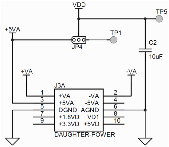
    4. VDD: To supply 3.3V you need to remove JP4. Then supply 3.3 from an external source to TP5 OR use a jumper from pin 9 on the Daughter-Power Header (J3A) to the middle pin of JP4.

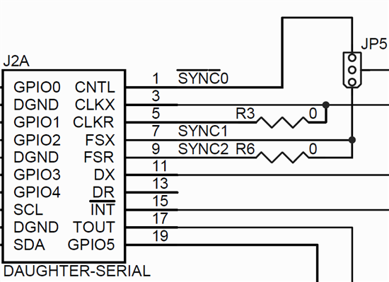
           5. SYNC: JP5 depends on which pin you want to use to control SYNC. On the Daughter-Power Header (J2A) pin 1, pin 7 or pin 9.


    DAC8562 Software Setup

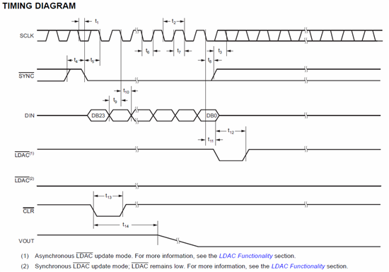
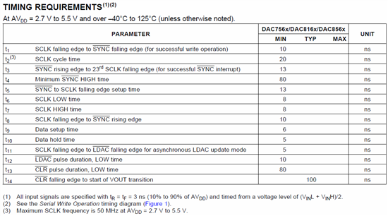
    1. TIMING REQUIREMENTS: Please take a look at the timing requirements. For your application you can ignore \LDAC and \CLR since they are both tied HIGH.

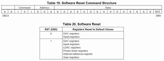
             2. SOFTWARE RESET: After power-on it is good practice to trigger a software reset. The bit RST should be set  to 1 on this first time software reset.


            3. INTERNAL REFENCE ENABLE: After the software reset, the internal reference must be enabled for use.

            4. GAIN ENABLE: Enabling the internal reference sets the gain of the DAC outputs to 2. To set them back to a gain of 1, the bits DAC-B and DAC-A must be set to 1.

            5. DAC DATA REGISTER: After this setup the device is ready to receive data and update its output. Please take a look at the table and pick the commands that you                wish to write to the DAC.

    Please let me know if you need any more specific details.

  • Eugenio,

    Many thanks for the detailed explanation. I've performed these steps in order to get a correct value on DAC-A output.

    1. Set SCK at 16MHz
    2. do a complete reset (CMD:0b101, DATA: 0b1)
    3. set the Internal Reference (CMD:0b111, DATA: 0b1)
    4. set the DAC Gain=1 (CMD:0b000, DATA: 0b1, ADDR: 0b010)
    5. configure software LDAC (CMD:0b110, DATA: 0b1)
    6. write data (CMD:0b000, DATA: 16-bit value, ADDR: 0b000)
    7. Repeat 6

    Regards,
    gaston