This thread has been locked.

If you have a related question, please click the "Ask a related question" button in the top right corner. The newly created question will be automatically linked to this question.

TVP5151 problem on s1d13515

Other Parts Discussed in Thread: TVP5151

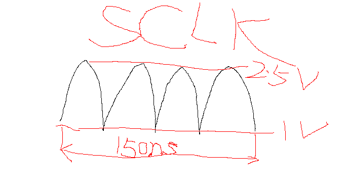
hardware : tvp5151 +  epson s1d13515

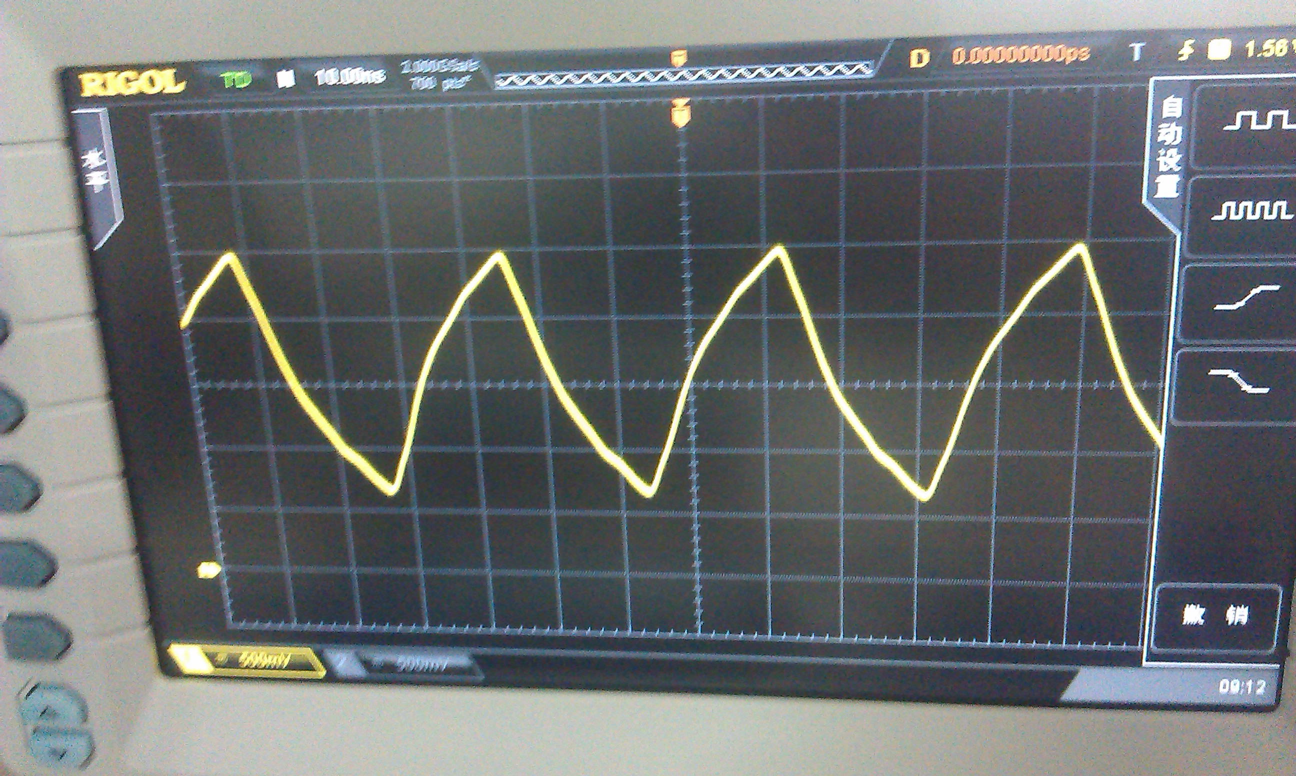
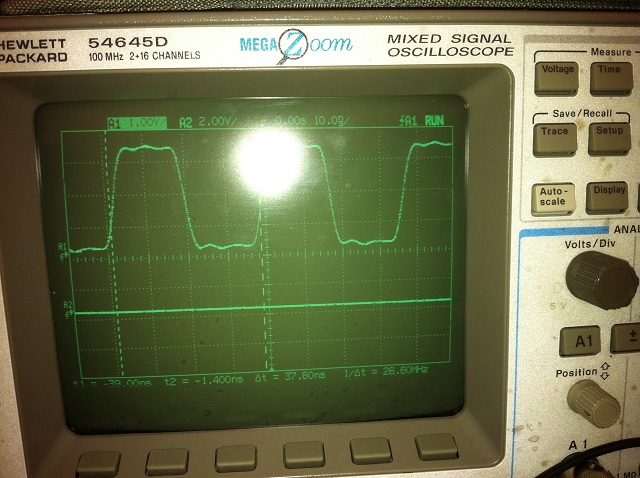
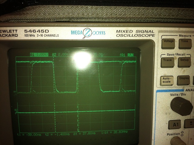
use tvp5151 to convert pal to ycbcr and then epson to convert ycbcr to rgb

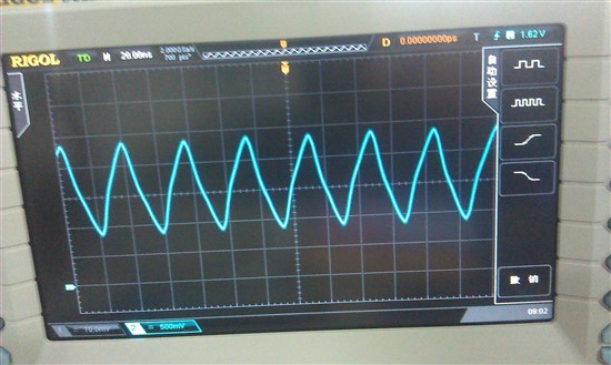
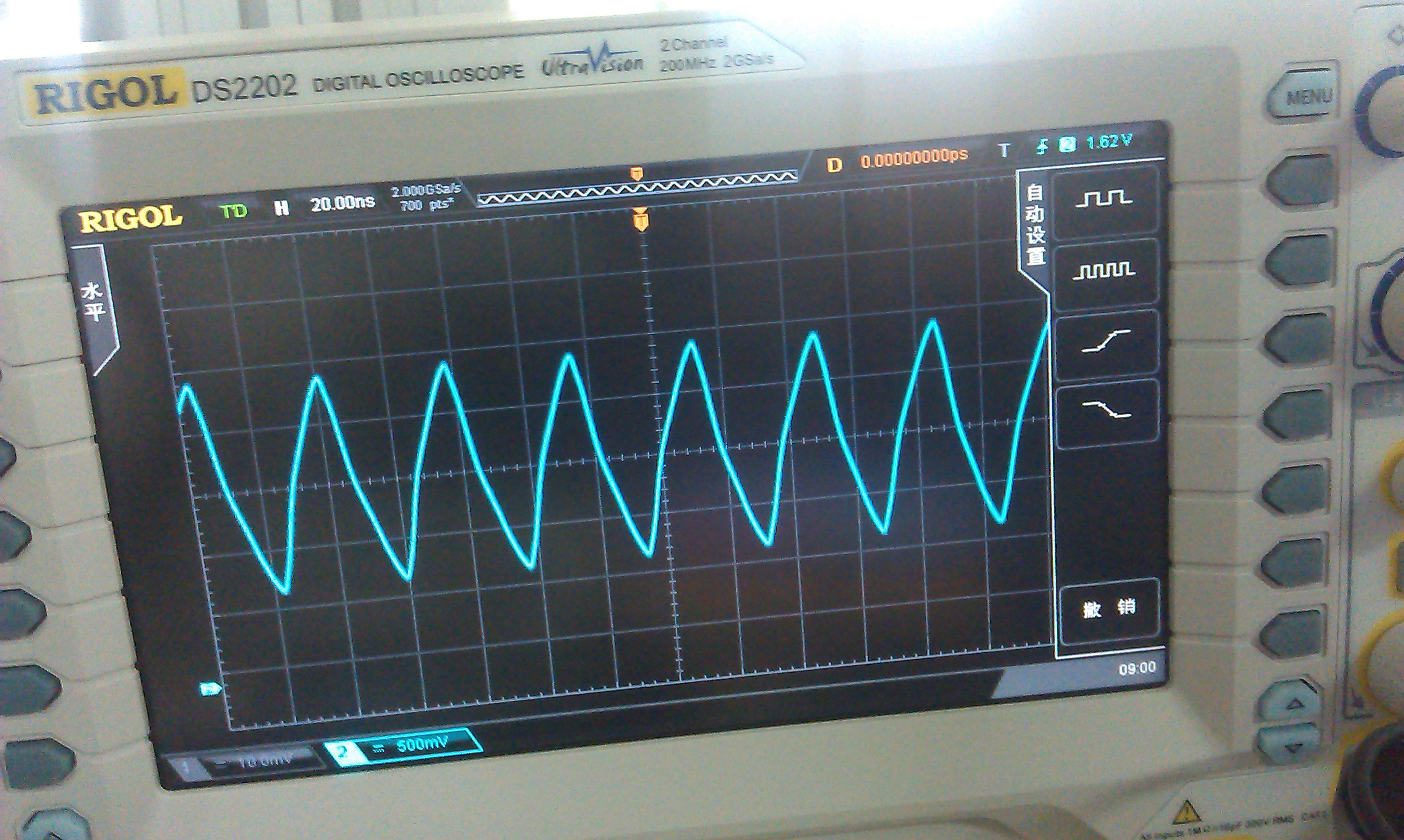
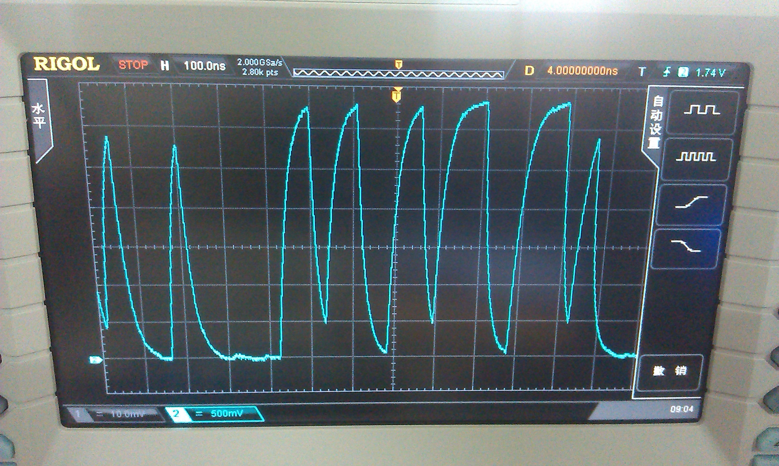
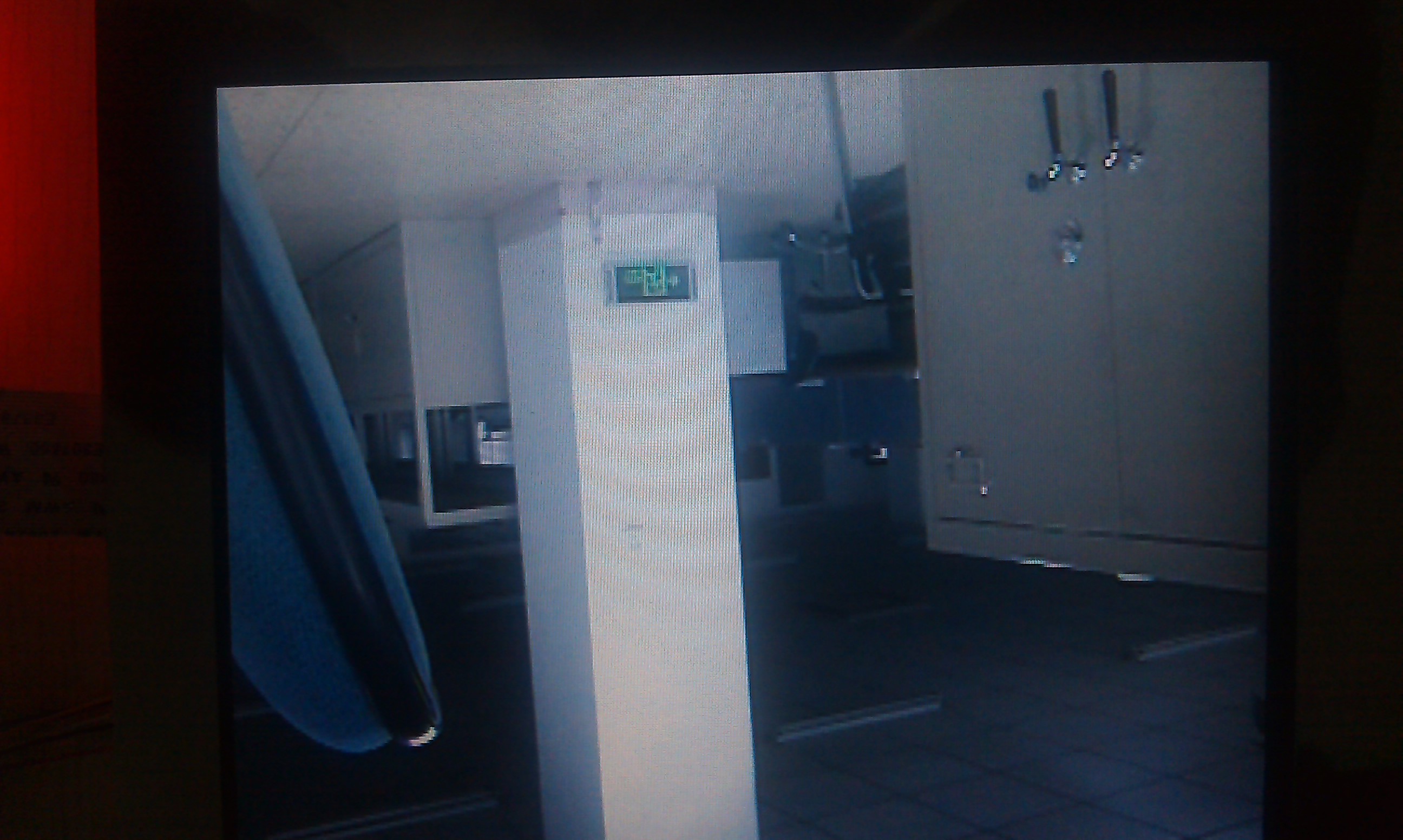
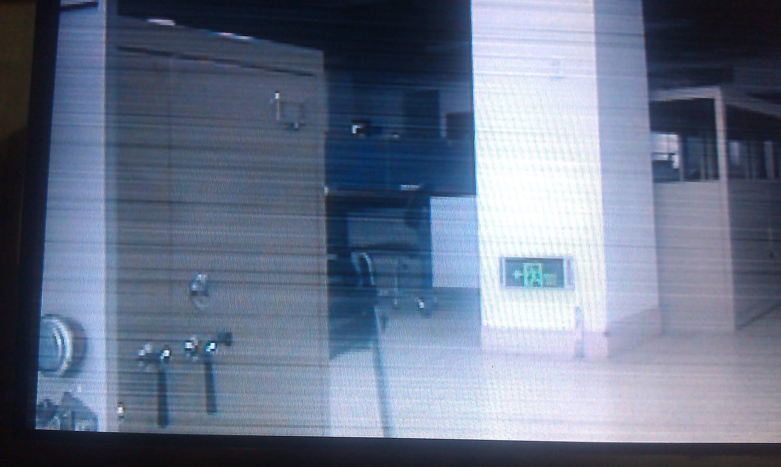
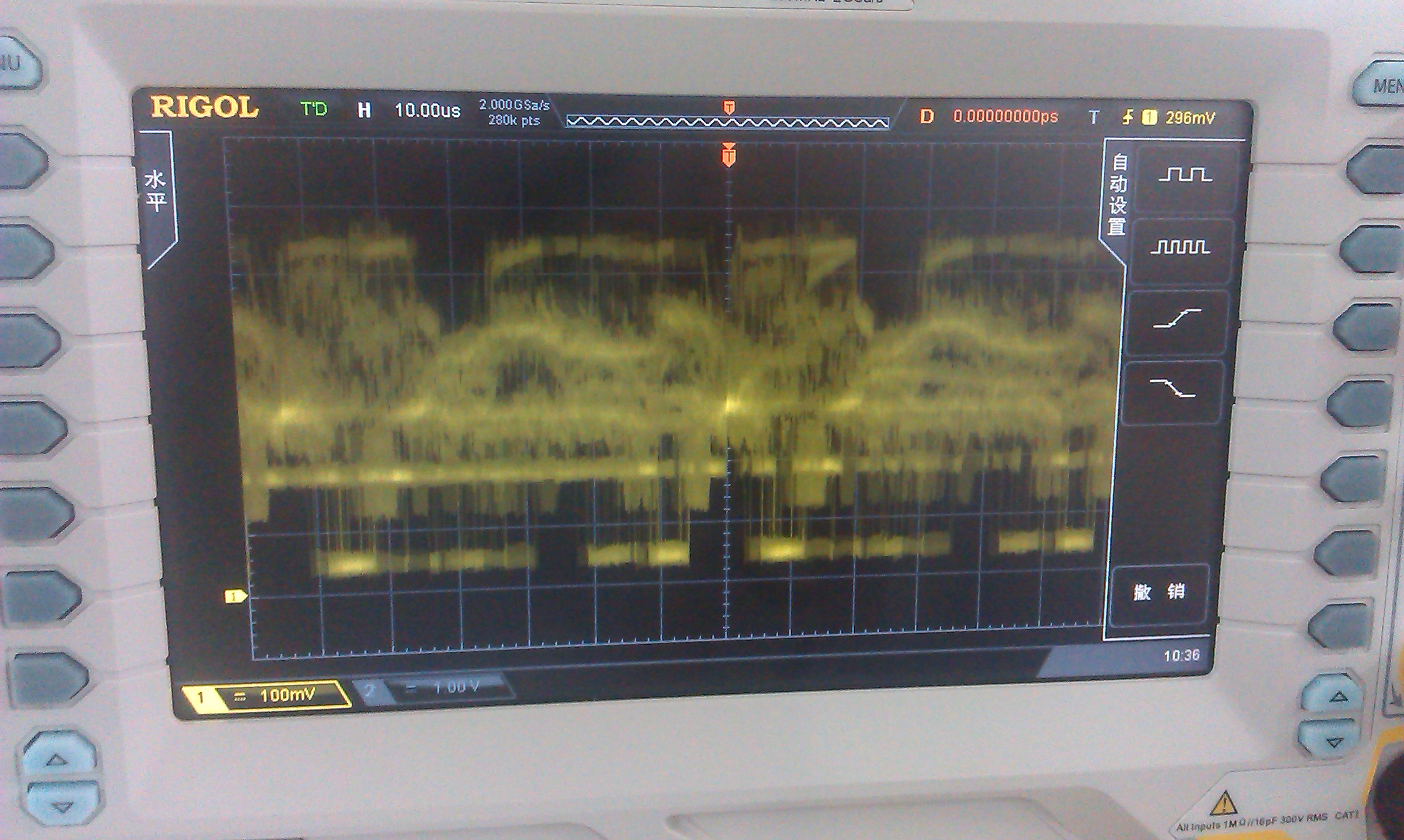
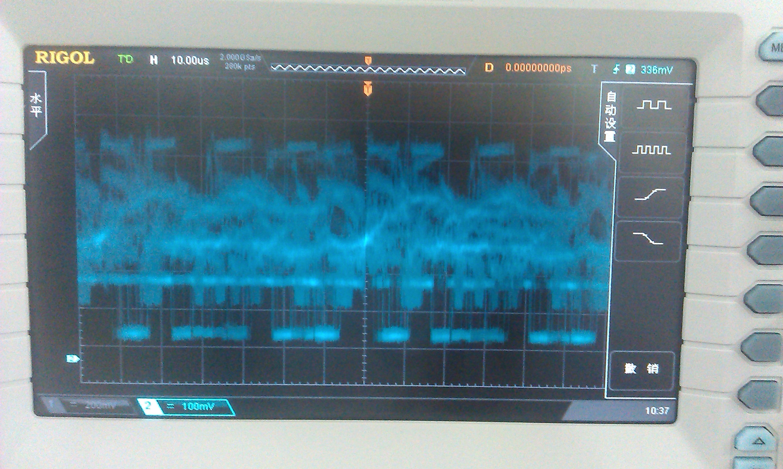
there is always one frame on the lcd screen when power on and then always the image ,occasionally, the oscilloscope probe touch the osc of TVP5151(27MHz), the frame change to another ,but still only one frame, and if i do it again ,then video changes to another frame(only one frame).The status registers of TVP5151 are as follows(some registers changes during the  time i record it):

0x85 = 0x71
0x88 = 0x6e
0x89 = 0x38
0x8A = 0x1b
0x8B = 0x87
0x8C = 0x83

0x84 = 0x2
0x85 = 0x71

0x88 = 0x70

0x89 = 0x8

0x8A = 0x1b

0x8B = 0x9d

0x8C = 0x83


0x8B = 0xd4
0x8B = 0x32

I am not familiar with VIDEO, and my English is not good.Maybe i describe my problem clearly, I hope your help, thank you

  • I use tvp5151 expamle1 to output BT656 format with embedded syncs.

  • What registers do you program at the start?

    the status registers show the signal is locked, but you only displayed part of the vertical count register so I can't check it.

    Did you set register 89h?

    Initially I recommend leaving all registers at their default and only set register 00h bit 1 to select the source input, and register 03h bit 0 & bit 3 to enable the outputs.

    Are your IO voltage levels correct so that they correspond to what the Epson device needs?

    Is the clock output toggling?

    Are the data outputs toggling?

    BR,

    Steve

  • I use the expamle1 in TVP5151 refrence manual.

    reg(0x00) = 0x00h ,use CVBS in AIP1A

    reg(0x03) = 0x09, YCbCr output enable and SClK enable

    I didn't set reg 0x89h, I only read it back.

    what may happen if singal is locked. which more register should i provide to check the problem?

    what do clock & data output toggling mean........ Is it mean the output of clock & data pin seem to work well with voltage go high and low?

    The SCLK pin output 27MHz with low voltage 1v and high voltage 2.5v

    And I donot know whether the wave on the data pin YOUT[0:7]  correct or not,  there's waves on the output pin

  • If the output SCLK is only reaching 1V and 2.5V then you probably have something loading the signal. This output should swing closer to 0V and 3.3V assuming your IO voltage is set to 3.3V.

    Can you send an oscilloscope capture of the SCLK output and another of one of the data output pins please?

    If the signal is locked it means the input is good and detected correctly.

    Yes, 'toggling' means switching from high to low. We are just looking to make sure they go high and low fully. We don't care about the 8 bit values at the moment.

    Can you send your schematic?

    BR,

    Steve

  • 5857.Schematic1.pdf

    I am at home now and i can only send  the oscilloscope capture  tomorrow.but i can draw a image ,i still remember the SCLK wave,  then i will send the data output  tomorrow to you.

  • Please make oscilloscope captures on both sides of R111.

    Remove R111 and make a third capture of the direct output of the TVP

    BR,

    Steve

  • The oscilloscope of our team is broken down and today i borrow another one. The pictures are the information for SCLK and data pins before and after removing the R111.Thank you 

    Best Regards

    XiaoQi

    sclk_behind_R111

    sclk_front_R111

    data

    Sclk_remove_R111

    PAL_signal

  • Either your power supplies are bad or you have something loading the outputs.

    Make sure that the oscilloscope impedance is NOT set to 50R.

    Check all your power supplies at the TVP pins when video is active.

    Clock should look like this...

    Data should look like this...

    These were taken on the EVM with a load on the output so with no load they would look even better.

    BR,

    Steve

  • Steve:

    I have solved my problem. The problem is on the power chip. Some pins of the power supply are abnormal. I changed a power chip and the problem was solved. However, another problem appeared. There are two Tvp5151 on my borad. One works well, but another with much noise that the display on the screen flicker with several wide blank line. Is any way to solve this problem.

    Best Regards,

    XiaoQi

  • I need a lot more information on the issue.

    My guess is that something else in your circuit is wrong.

    Please check all supplies very carefully. Check all component values are correct as per the datasheet example application circuit.

    Can you capture oscilloscope traces of about 100us at the video input pin of each of the good and bad TVP?

    Can you canture a picture of the 'bad' display?

    BR,

    Steve

  • Steve:

    I have checked the circuit concerned with the TVP5151 and it seemed to be all correct. One colleague told me it may be a problem on hardware. The signal on the line is interfered by others, but he checked the circuit for a whole day and he still didnot find the interference souce. This is the signal of good and bad  and the input video signal.

    BG,

    XiaoQi


     The good image


    The bad image


    The good video input signal


    The bad video input signal


  • Move the scope trigger point down so that it only catches the low going sync tip hence will display a stable line image. This will make the scope captures much easier to see.

    As a test try swapping the good and bad inputs to the TVP. This can be achieved by lifting the TVP input coupling capacitors and re-soldering them in an upright orientation, then bridge a wire from the now floating top of the capacitor to the alternate TVP input capacitor pad. This will help determine if the root cause is before or after the input coupling capacitor.

    BR,

    Steve

  • I bridge wires from the bad signal to the good signal input, but the result is still bad.  There's another phenomenon, if  i  turn on both the  TVP5151s, the good signal becomes bad and the bad signal becomes even worse. The two TVP5151s share the same power supply. What may be the problem?

    Best Regards,

    XiaoQi

  • If the 'good' channel is good with one input but bad with another input then the input part of the circuit is bad, not the TVP.

    Did you lift the input coupling capacitors when you did this experiment or did you simply connect wires?

    Please re-send the original oscilloscope captures but with correct triggering so we can see a clear video signal.

    Please also measure the power supply noise. If you suspect the power, then check it :)

    BR,

    Steve