This thread has been locked.

If you have a related question, please click the "Ask a related question" button in the top right corner. The newly created question will be automatically linked to this question.

TLV431B

Other Parts Discussed in Thread: TLV431B

Hello everyone,

I use the TLV431B in the following configuration:


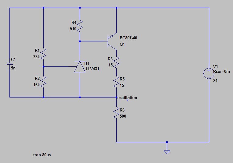
Transistor Q1 is used to drive high currents up to 100mA (TLV431B can drive maximum 15mA).

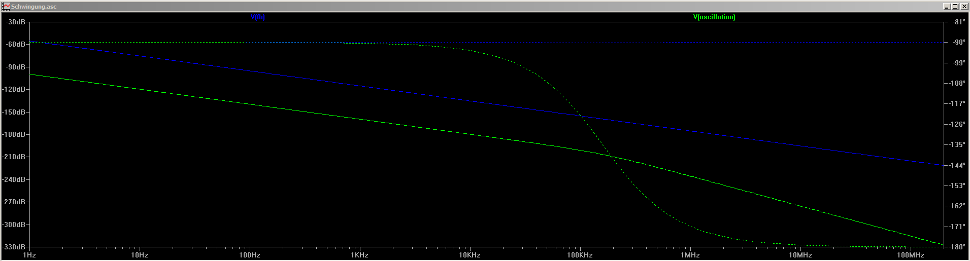
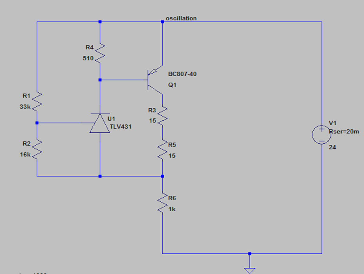
But, at high load currents(small R6), there is a oscillation at the marked point in the picture (above R6)!

It looks like an stability problem. Can anyone explain this?

Is there a good spice-model of the B-Variant available?

Thanks for your help!!!


  • Nico,

    Models can be found here. Search page for TLV431B
    http://www.ti.com/adc/docs/midlevel.tsp?contentId=55102

    C1 creates an output pole causing oscillation. I see two solutions.
    1) Remove C1.
    2) Add properly sized capacitor in parallel with R1. (lead/lag with R1 and R2)

    For parallel cap, try C = 1/(6.28 * Fosc * 33,000) or a little larger; Fosc = oscillation frequency.

  • Hello Ron,

    thank you for the fast answer.

    1.) Removing C1 is not possible for my application.

    2.) It seems, that oscillation is getting better by adding a C in parallel to C1. But how can I justify that mathematicaly or with theory of poles and zeros. Can I derive an expression for zeros and poles?

    Thank you in forward!!!

    Regards Nico

  • Nico,

    Increase C1 will decrease the output pole frequency (output impedance and C1). By 'better' do you mean lower amplitude oscillation or no oscillation? The formula for the 33k shunt cap, is based on setting a zero at the oscillation frequency to improve phase margin at the problematic frequency.

  • Hi Ron,

    thank you for your answer.

    yes, by 'better' i mean no oscillation. You mean the dominant pole is formed by the output resistance of TLV431B plus reistor R4 and C1? Is it not more complecx because the OpAmp drives an NPN-Transistor and the circuit uses also Q1 for regulation. All these devices influence the frequency response, or am I wrong? Ideally i should look at the Bode-plot of the open-loop to see where i must set my zero with a C parallel to C1.

    Why can you say, I must regarde the osillation frequency to set my zero? I can not follow.....

    Best regards

    Nico 

  • Use a Type II compensator. The following app notes provide all the info you need.

    http://switchingpowermagazine.com/downloads/15%20Designing%20with%20the%20TL431.pdf

    http://www.irf.com/technical-info/appnotes/an-1162.pdf

    http://m.eet.com/media/1157551/c0993posted.doc

  • Nico,

    The sum TLV431B and current boost PNP have a pole with C1. Running a bode plot would be informative; “breaking the loop” at R1 top and moving load resistor to other side so the circuit can be grounded will make getting a bode plot easier.


  • Hello,

    thank you for the support. I have tried to simulate the freqnency response and bode-plot in spice (LTspice).

    But that results in a not plausible bode-plot.

    First my simulation build Up:

    I have inserted the load at the suggested place.

    I have break up the loop at its feedback point and feed in at the Feedbackpoint, using very big Ls and Cs to establich the DC-condtions. Yes, this method is not 100% correct, but sufficient for my purpose to get an qualitative bode-plot.

    But for me, that results in a not plausible bode-plot:

    Very low Gain an only 90° phase-shift? It does not make sense, or am i wrong?


    regards, Nico

  • Nico,

    The gains don't make sense like you said.
    Try a DC analysis to make sure the voltages and currents are correct.