Maybe somebody here can help me solve this problem.
I'm running the evaluation module for the ads7881, but my usable input range is restricted to ~500-600mV of the 2.5V swing. If I input just a DC signal and sweep it from 0-2.5V, the ADC codes roll over (i.e. I reach my max code of 4092, and then it overflows to 0 and beyond, or vice versa) several times. All in all I only get about 600mV of range at any part of the full scale range. At the top (2.5V) and bottom (0V) I reach codes 4092 and 0, respectively, and there is no further overflow.
What I'm trying to do is put a 0-4V 500kHz signal into the board. I feed it into an inverting input stage which outputs -2.5-0V, which is then fed into the board's signal conditioning stage. I've tried changing the input DC offset, the the input amplifier's offset pot (R25), as well as changing the the input impedance. I experience the same behaviour if I simply feed the board with a DC voltage from a bench supply.
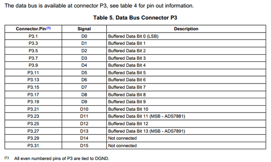
I'm driving the board in back-to-back mode with a 2MHz clock to CONVST, with CS and RD tied low. Byte is tied low, PWD/RST and A_PWD are tied high. The reference voltage is produced using the on-chip refout, and is measured to be 2.5V. The +/-12V and +5V rails also measure up correctly. When I measure the input voltage at the output of the signal conditioning stage (U2 pin 6) I seem to be getting the correct 0-2.5V input to the ADC. Otherwise I am using all of the default jumpers and settings.
Note that I'm using the board standalone, not via a 5-6K+DSP setup. As such I'm not using the address decoder chip, but rather driving the control pins directly from J3. I have noticed, however, that the decoder chip U8 gets a bit warm (not hot) while running. Perhaps this is related somehow?
I've been through the datasheets, but I don't see anything that would be related to this overflow behaviour. Perhaps I'm misunderstanding how the board is supposed to operate, but I'm a bit stumped now.


