This thread has been locked.

If you have a related question, please click the "Ask a related question" button in the top right corner. The newly created question will be automatically linked to this question.

ADS 1148 data rate

Other Parts Discussed in Thread: ADS1148, ADS1248, ADS1247

Hi all,

I am developing an equipment that uses three ADS1148. I need to measure the temperature by using 20x pt1000 sensors, so I will MUXing channels. I am limited by time for one measuring and writing results (20 temp values + time) to FLASH memory.

So my question. I was reading datasheet and looking the table 12 (Data Conversion Time), but I don't know how to choose the Nominal Data Rate (SPS)? If I choose a higher value (20kSPS) the conversion time is shorter. But what is the problem of these higher (or lower 5SPS) values of SPS?

I am sorry for my bad English skill.


Thank you to all,

VojK

  • Hi VojK,

    With many of the precision data converters, you trade data rate for noise level and precision.

    If you look at the ADS1148 datasheet, you can see this in Tables 1 and 2. As you go higher in SPS, your noise level becomes higher. Since the ADS1148 is only a 16-bit part, you don't see as much change in the lower levels of the data rate.

    If you look at the 24-bit equivalent ADS1248, the noise levels are shown in similar tables and you can see clear changes in the noise performance against the data rate.

    Joseph Wu

  • Hi Joseph,

    Thank you. Your reply is helpful for me!

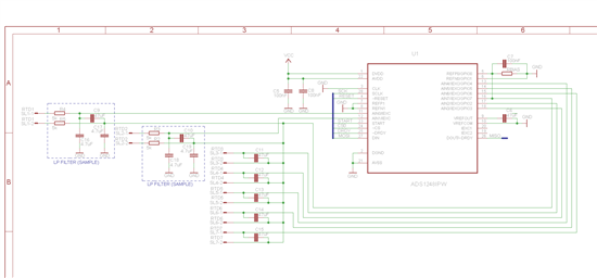
    I designed the first version of the scheme with ads1248. This circuit works with 7 RTDs (Pt1000) in 2-wire conection. AIN7 is the common pin. Device will be supplied by 3,6V battery (it does not matter now). Two input LowPass filters are in scheme only for example. SL1 - SL7 are connectors for RTDs.

    Could someone with more experience check this circuit please (like blocking capacitors, etc.)? Is it necessary to use a LowPass filter on pins REFP0 - REFN0?

    Thank you for all comments!

    VojK

  • VojK,


    In general, your schematic looks ok. There are 7 two-wire ratiometric measurements possible with RBIAS for REF0. The input capacitances used at AIN1 (both the common-mode and differential) look large to me. You can compare those values to the ones used in the ADS1248EVM.

    Note that you only need to have one capacitor off of AIN7. For example C17 and C19 are duplicates AINN differential capacitor of the LP filter (you don't want 7x capacitors on the AINN node).

    THe REFOUT capacitor is 47uF which is ok, but remember that this will take some settling time at turn-on. This is described on page 29 of the datasheet. Filtering on REF0 can be used if desired.

    If you are in need of further information, there are many good descriptions and examples in application note sbaa201 in the website below:

    http://www.ti.com/lit/an/sbaa201/sbaa201.pdf

    There is also a reference design writeup that includes RTDs and the ADS1247 at the following site:

    http://www.ti.com/lit/ug/slau520a/slau520a.pdf


    Joseph Wu