


Dear Colleagues,
First of all thanks for the opportunity to share my doubts in the community.
I have to develop an equipment with 3 x ADS1282 IC’s, acquiring data simultaneously. I intend to use only one SPI interface for data exchange between the microcontroller and ADS1282, so I found a suggestion by Christopher in the following link: http://e2e.ti.com/support/data_converters/precision_data_converters/f/73/p/291510/1018745.aspx#1018745
Seems to be very interesting to MUX the SCLK for both devices to “gate” the SPI communication. My only concern is about Synchronization, in my device it’s very important that the acquisition for both 3 ADS1282 starts at same time, in this case should I use Pulse-Sync mode and a common output in my MCU to control the SYNC pins of my ADS1282 (I’ll use the same oscillator 4.096MHz master clock for all ADS1282)?
I want to use only one data ready “DRDY” output to trigger an interruption in my microcontroller and the ADS1282 has to read the data in continuous mode. If I set properly all 3 ADS1282 (1- Power on; 2- SDATAC command; 3- Write/Read registers (250SPS); 4- RDATAC command; 5- Sync pin event) should all DRDY output goes low at the same time (for 250SPS each 4ms)?
Print screen for logic data of ADS1282EVM-PDK reading data in continuous mode:
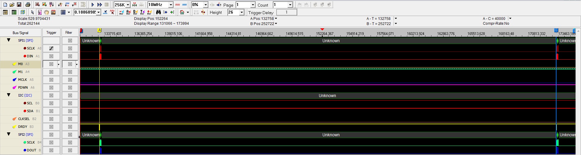
At this moment I can’t read the data DOUT at same time (using a LV4052 MUX), but even sending SCLK transitions IC per IC to read the data, should the DRDY output goes low at same time after next conversion?
In the ADS1282 datasheet pag.:27 says: “When reading data by the continuous mode, the data must be read within four CLK periods before DRDY goes low again or the data are overwritten with new conversion data”. It means I need to read all 32 data bits 4 CLK periods before DRDY goes low again, in my case 250SPS I have approximately 4ms to read the data, so even using a LV4052 MUX to read the data IC per IC, I still have enough time because my SCLK frequency is around 2MHz?
DRDY resets high on the first falling edge of SCLK, in my case the SCLK signal is MUX so DRDY for the last IC will take longer to reset high, even doing in this way I still have the conversion for all IC’s synchronized and the DRDY output goes low at same time after next conversion?
Best Regards
Flávio Cavalieri

