This thread has been locked.

If you have a related question, please click the "Ask a related question" button in the top right corner. The newly created question will be automatically linked to this question.

ADS54RF63EVM LVDS output problem

Other Parts Discussed in Thread: ADS54RF63EVM

Hi

I am interfacing the ADS54RF63EVM with the ML605 FPGA board. Glitches were seen when digitizing a sinusoidal input so I ended up having a look at the LVDS outputs and I see some strange behaviour as the sampling rate is increased.

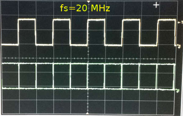
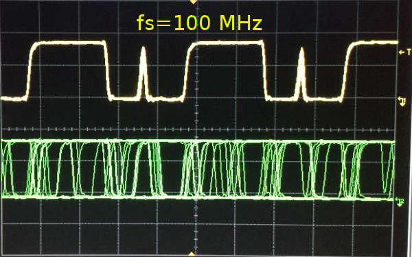
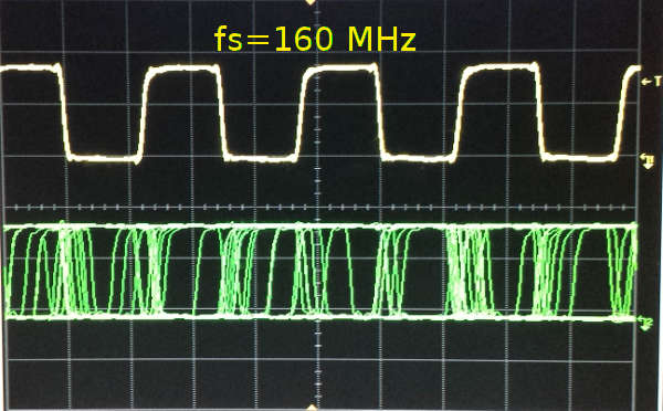
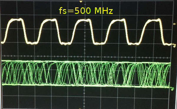
The oscilloscope screenshots below are for a 1.5 Vpp input clock and -1dBFS input sinusoid with frequency 15.5 mHz, just as the EVM user guide suggests. The top signal is the DRY output and the bottom is the LSB LVDS line, with some persistence. This is not what the datasheet suggests the output looks like and this is the second ADS54RF63EVM that we have tried showing this problem.

Can you suggest where the problem lies?

  • Hi,

    No, i can not think of anything that should cause glitches on the DRY signal nor the lsb data transitions to be so uncorrelated to the transitions of DRY. Since you are using the EVM, there shouldn't be anything that you could be doing that would cause this, and every EVM is tested at max sample rate before it is stocked for shipping.

    What type of scope are you using, please, and what type of probe?  High impedance differntial probe?  Triggered on rising edge of DRY?  The scope shots show something at the lower right portion of the trace that looks like a 'ground' indication, but that doesnt make sense.  These are LVDS signals, with an output swing biased to about 1.2V.  What does that little symbol represent?

    Do you have the FPGA programmed to implement the 100 ohm termination on the LVDS pairs that the LVDS output drivers require?  (although that would not explain why the 20MHz case looks good).  Also, i believe the lower spec limit for sample rate is 40MHz.

    May i see a scope capture of the input clock in front of the ADC as well?

    Regards,

    Richard P.

  • It is working now.

    My problem was that I assumed that the 100 ohm resistors were implemented on the ML605 PCB and so the FPGA was not programmed to terminate the LVDS lines properly. The DRY signal happened to be properly terminated within the PLL.

    Thank you for your help!