This thread has been locked.

If you have a related question, please click the "Ask a related question" button in the top right corner. The newly created question will be automatically linked to this question.

why the the voltage value of sampling site is different?


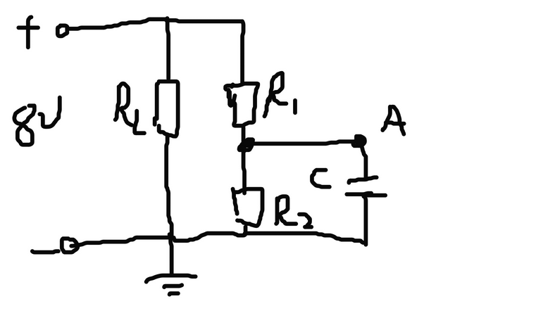
As shown in the figure, R1  is 100K, R2 is 50K. “A” is a sampling site. If circuit has “c”,  The  voltage value of sampling site is 1.7V. If circuit  does not have “c”,  The  voltage value of sampling site is 1.43V. Voltage is measured by multimeter.That is why?

  • Hi User4245245,

    Welcome to the forum. If you have applied 8V to this circuit and you have no connection issues then you should see 1/3 of the input voltage dropped across R2.  This assumes that your voltage source is not current limited. This voltage across R2 should be about 2.67V. 

    It appears that you may either have a connection issue, or your multi-meter does not have a high impedance input.  If the meter is drawing current that is significant relative to the voltage being measured, you will create a current divider.  This in turn will lower the voltage being measured.  Sometimes addinig a capacitor will allow enough charge to be stored limiting the current divider effect.  Can you tell me more about your circuit?  What is the value of RL and C?  Is A connected to any other device, like an ADC?

    Best regards,

    Bob B