Hi,
I am a student and want to make a pulsoximeter and meet some difficulty.
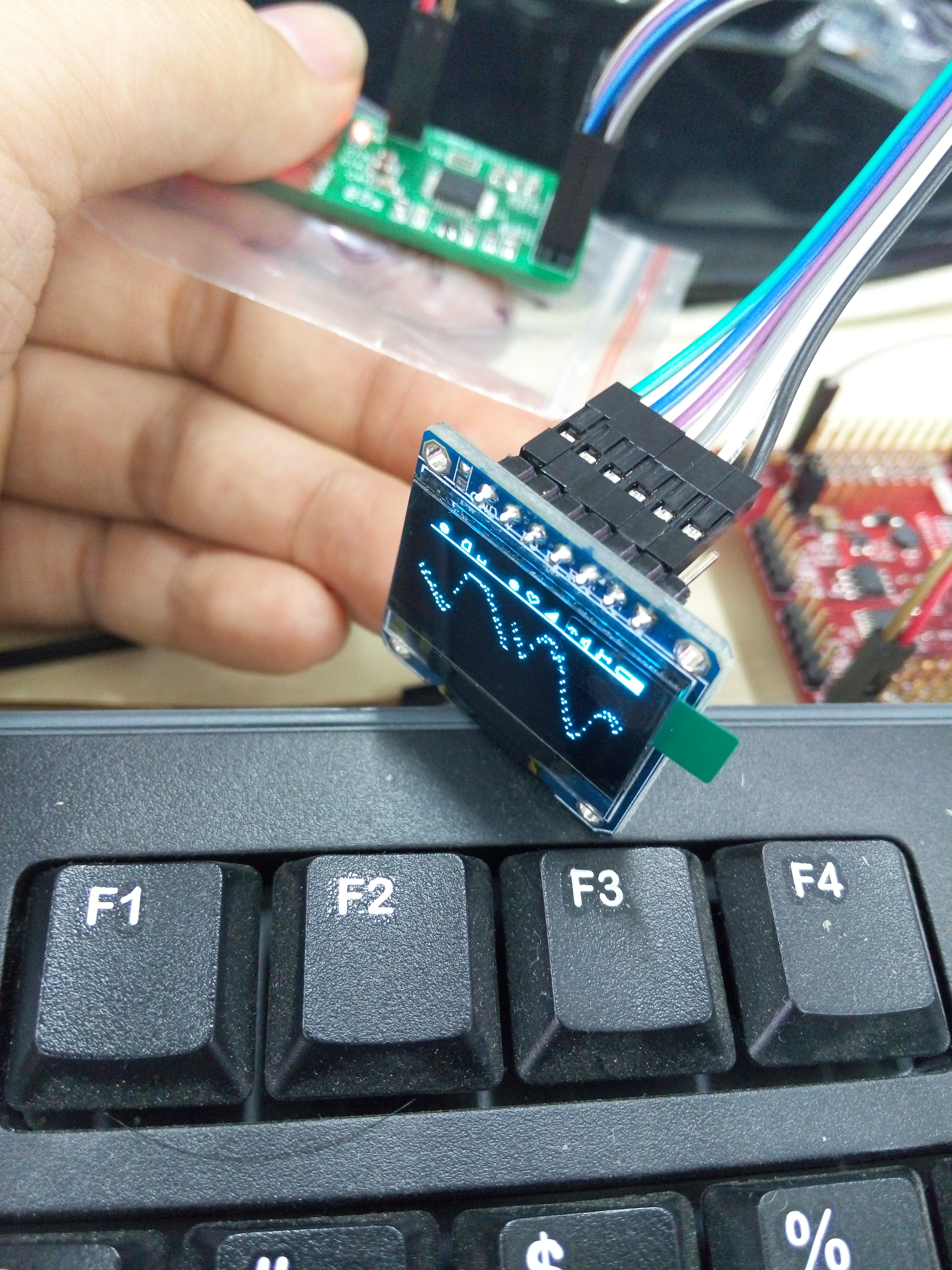
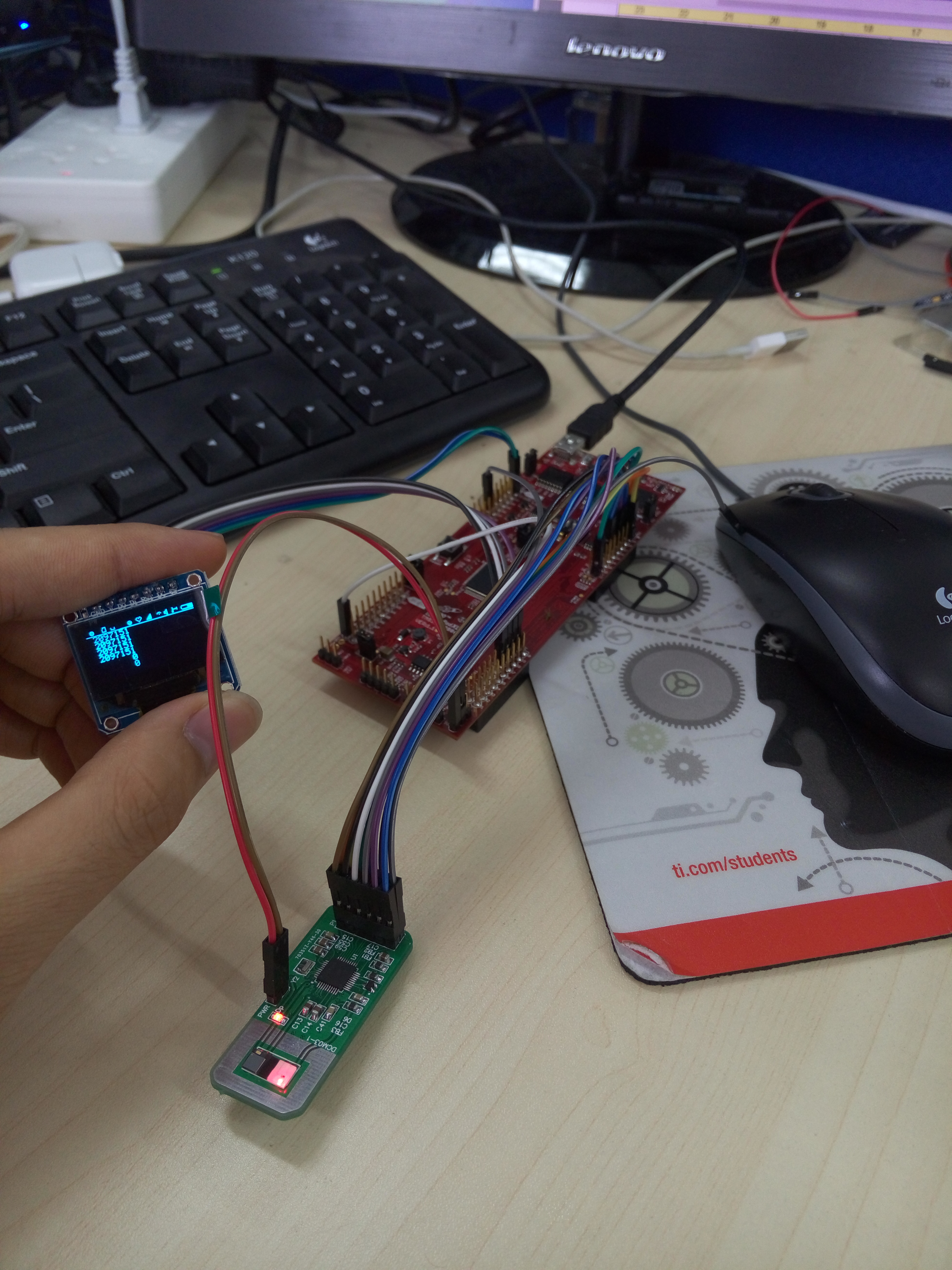
I make the AFE4400 board myself because the AFE4400SPO2EVM board is expressive for me.
I use the DCM03 as the sensor and the MCU is TMS320F28069 which I am familiar with.
I put the schematic and my project as the attachment.
I refer to the AFE4400SPO2EVM board in both schematic and codes.
What I have complete:
1.The SPI module can work and I try to write and read back the registers and the values are correct;
2.After initialization, I measure the voltage on some pins:
a) 0.494V on TX_REF pin (pin#9)
b) 0.966V on BG pin (pin#7)
c) 0.886V on VCM pin (pin#4)
But I think the TX_REF should be 0.75v.
I notice that if I don't write to the CONTROL2 (Address = 23h, Reset Value = 0000h)register with 0x020100(0000 0010 0000 0001 0000 0000) then the TX_REF voltage will be 0.75v.
Why?
3.After initialization, I try to read back some values:
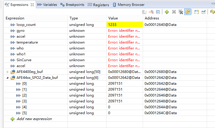
	   AFE44xx_SPO2_Data_buf[0] = AFE44x0_Reg_Read(42);  //read RED Data
	   AFE44xx_SPO2_Data_buf[1] = AFE44x0_Reg_Read(43);  //read Ambient data
	   AFE44xx_SPO2_Data_buf[2] = AFE44x0_Reg_Read(44);  //read IR Data
	   AFE44xx_SPO2_Data_buf[3] = AFE44x0_Reg_Read(45);  //read Ambient Data
	   AFE44xx_SPO2_Data_buf[4] = AFE44x0_Reg_Read(46);  //read RED - Ambient Data
	   AFE44xx_SPO2_Data_buf[5] = AFE44x0_Reg_Read(47);  //read IR - Ambient Data
When my finger is NOT on the DCM03, the values are shown below:
When my finger is on the DCM03, the values are shown below:
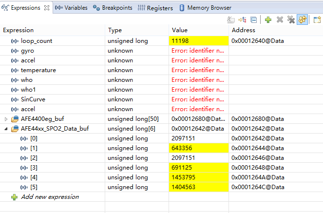
As you see, the RED Data and IR Data are always as 2097151.
Why?
4.The initialization codes:
The code example for the AFE4400SPO2EVM board is for AFE4490 so I change some codes.
/**********************************************************************************************************
*	        AFE44xx default Initialization          				                  					  *
**********************************************************************************************************/

void AFE44xx_Default_Reg_Init(void)
{
  Disable_AFE44x0_SPI_Read();

  //Pulse Repetition Period Count Register:399999
  AFE44x0_Reg_Write((unsigned char)PRPCOUNT, (unsigned long)PRP);

  //Sample LED2 Start Count Register:30080
  AFE44x0_Reg_Write((unsigned char)LED2STC, (unsigned long)LED2STC_VAL);
  //Sample LED2 End Count Register:37998
  AFE44x0_Reg_Write((unsigned char)LED2ENDC, (unsigned long)LED2ENDC_VAL);
  //LED2 LED Start Count Register:30000
  AFE44x0_Reg_Write((unsigned char)LED2LEDSTC, (unsigned long)LED2LEDSTC_VAL);
  //LED2 LED End Count Register:37999
  AFE44x0_Reg_Write((unsigned char)LED2LEDENDC, (unsigned long)LED2LEDENDC_VAL);

  //Sample Ambient LED2 Start Count Register:80
  AFE44x0_Reg_Write((unsigned char)ALED2STC, (unsigned long)ALED2STC_VAL);
  //Sample Ambient LED2 End Count Register:7998
  AFE44x0_Reg_Write((unsigned char)ALED2ENDC, (unsigned long)ALED2ENDC_VAL);

  //Sample LED1 Start Count Register:10080
  AFE44x0_Reg_Write((unsigned char)LED1STC, (unsigned long)LED1STC_VAL);
  //Sample LED1 End Count Register:17998
  AFE44x0_Reg_Write((unsigned char)LED1ENDC, (unsigned long)LED1ENDC_VAL);
  //LED1 LED Start Count Register:10000
  AFE44x0_Reg_Write((unsigned char)LED1LEDSTC, (unsigned long)LED1LEDSTC_VAL);
  //LED1 LED End Count Register:17999
  AFE44x0_Reg_Write((unsigned char)LED1LEDENDC, (unsigned long)LED1LEDENDC_VAL);

  //Sample Ambient LED1 Start Count Register:20080
  AFE44x0_Reg_Write((unsigned char)ALED1STC, (unsigned long)ALED1STC_VAL);
  //Sample Ambient LED1 End Count Register:27998
  AFE44x0_Reg_Write((unsigned char)ALED1ENDC, (unsigned long)ALED1ENDC_VAL);

  //LED2 Convert Start Count Register:6
  AFE44x0_Reg_Write((unsigned char)LED2CONVST, (unsigned long)LED2CONVST_VAL);
  //LED2 Convert End Count Register:9999
  AFE44x0_Reg_Write((unsigned char)LED2CONVEND, (unsigned long)LED2CONVEND_VAL);

  //LED2 Ambient Convert Start Count Register:10006
  AFE44x0_Reg_Write((unsigned char)ALED2CONVST, (unsigned long)ALED2CONVST_VAL);
  //LED2 Ambient Convert End Count Register:19999
  AFE44x0_Reg_Write((unsigned char)ALED2CONVEND, (unsigned long)ALED2CONVEND_VAL);

  //LED1 Convert Start Count Register:20006
  AFE44x0_Reg_Write((unsigned char)LED1CONVST, (unsigned long)LED1CONVST_VAL);
  //LED1 Convert End Count Register:29999
  AFE44x0_Reg_Write((unsigned char)LED1CONVEND, (unsigned long)LED1CONVEND_VAL);

  //LED1 Ambient Convert Start Count Register:30006
  AFE44x0_Reg_Write((unsigned char)ALED1CONVST, (unsigned long)ALED1CONVST_VAL);
  //LED1 Ambient Convert End Count Register:39999
  AFE44x0_Reg_Write((unsigned char)ALED1CONVEND, (unsigned long)ALED1CONVEND_VAL);

  //ADC Reset 0 Start Count Register:0
  AFE44x0_Reg_Write((unsigned char)ADCRSTSTCT0, (unsigned long)ADCRSTSTCT0_VAL);
  //ADC Reset 0 End Count Register:5
  AFE44x0_Reg_Write((unsigned char)ADCRSTENDCT0, (unsigned long)ADCRSTENDCT0_VAL);

  //ADC Reset 1 Start Count Register:10000
  AFE44x0_Reg_Write((unsigned char)ADCRSTSTCT1, (unsigned long)ADCRSTSTCT1_VAL);
  //ADC Reset 1 End Count Register:10005
  AFE44x0_Reg_Write((unsigned char)ADCRSTENDCT1, (unsigned long)ADCRSTENDCT1_VAL);

  //ADC Reset 2 Start Count Register:20000
  AFE44x0_Reg_Write((unsigned char)ADCRSTSTCT2, (unsigned long)ADCRSTSTCT2_VAL);
  //ADC Reset 2 End Count Register:20005
  AFE44x0_Reg_Write((unsigned char)ADCRSTENDCT2, (unsigned long)ADCRSTENDCT2_VAL);

  //ADC Reset 3 Start Count Register:30000
  AFE44x0_Reg_Write((unsigned char)ADCRSTSTCT3, (unsigned long)ADCRSTSTCT3_VAL);
  //ADC Reset 3 End Count Register:30005
  AFE44x0_Reg_Write((unsigned char)ADCRSTENDCT3, (unsigned long)ADCRSTENDCT3_VAL);

  //Control Register 0:0
  AFE44x0_Reg_Write((unsigned char)CONTROL0, AFE44xx_Current_Register_Settings[0]);            //0x00

  //Control Register 2:TX_REF_1 + RST_CLK_ON_PD_ALM_PIN_DISABLE +
  //ADC_BYP_DISABLE + TXBRGMOD_H_BRIDGE + DIGOUT_TRISTATE_DISABLE + XTAL_ENABLE
  //+ EN_FAST_DIAG + PDN_TX_OFF + PDN_RX_OFF + PDN_AFE_OFF)
  //0000 0010 0000 0001 0000 0000 = 0x020100
  //AFE44x0_Reg_Write((unsigned char)CONTROL2, AFE44xx_Current_Register_Settings[35]);           //0x23
  AFE44x0_Reg_Write((unsigned char)CONTROL2, 0x020100);

  //Transimpedance Amplifier Gain Setting Register
  AFE44x0_Reg_Write((unsigned char)TIAGAIN, AFE44xx_Current_Register_Settings[32]);            //0x20

  //Transimpedance Amplifier and Ambient Cancellation Stage Gain Register
  //AMBDAC_0uA + FLTRCNRSEL_500HZ + STAGE2EN_LED2 + STG2GAIN_LED2_0DB + CF_LED2_5P + RF_LED2_1M
  AFE44x0_Reg_Write((unsigned char)TIA_AMB_GAIN, AFE44xx_Current_Register_Settings[33]);       //0x21

  //LED Control Register
  //LEDCNTRL_VAL,0x011414, 0000 0001 0001   0100 0001 0100, 3.9mA
  AFE44x0_Reg_Write((unsigned char)LEDCNTRL, AFE44xx_Current_Register_Settings[34]);           //0x22

  //LEDCNTRL_VAL,0x107
  AFE44x0_Reg_Write((unsigned char)CONTROL1, AFE44xx_Current_Register_Settings[30]);           //0x1E

  Enable_AFE44x0_SPI_Read();
}

/**********************************************************************************************************
*	        AFE44xx_Read_All_Regs          				                  					  *
**********************************************************************************************************/

void AFE44xx_Read_All_Regs(unsigned long AFE44xxeg_buf[])
{
  unsigned char Regs_i;
  for ( Regs_i = 1; Regs_i < 50; Regs_i++)
  {
    AFE44xxeg_buf[Regs_i] = AFE44x0_Reg_Read(Regs_i);
  }
}
/*********************************************************************************************************/
/**********************************************************************************************************
*	        AFE44xx_PowerOn_Init          				                  					  			  *
***********************************************************************************************************/
void AFE44xx_PowerOn_Init(void)
{
  volatile unsigned short Init_i, j;
  Init_AFE44xx_Resource();
  for (j = 0; j < DELAY_COUNT; j++)
  {
    for ( Init_i =0; Init_i < 20000; Init_i++);
    for ( Init_i =0; Init_i < 20000; Init_i++);
    for ( Init_i =0; Init_i < 20000; Init_i++);
  }
  Init_AFE44xx_DRDY_Interrupt();
  AFE44xx_Default_Reg_Init();
}
I put the schematic and my project as the attachment.
I don't know it's a hardware problem or a software problem.
I really need your kind help.
Sorry for my poor English.
I am looking forward for your help.
:)
thanks and regards
Di