This thread has been locked.

If you have a related question, please click the "Ask a related question" button in the top right corner. The newly created question will be automatically linked to this question.

ADS1248 low pass filter SBAA201. Voltage offset created and latched resulting in erroneous measurements.

Other Parts Discussed in Thread: OPA2333, ADS1248

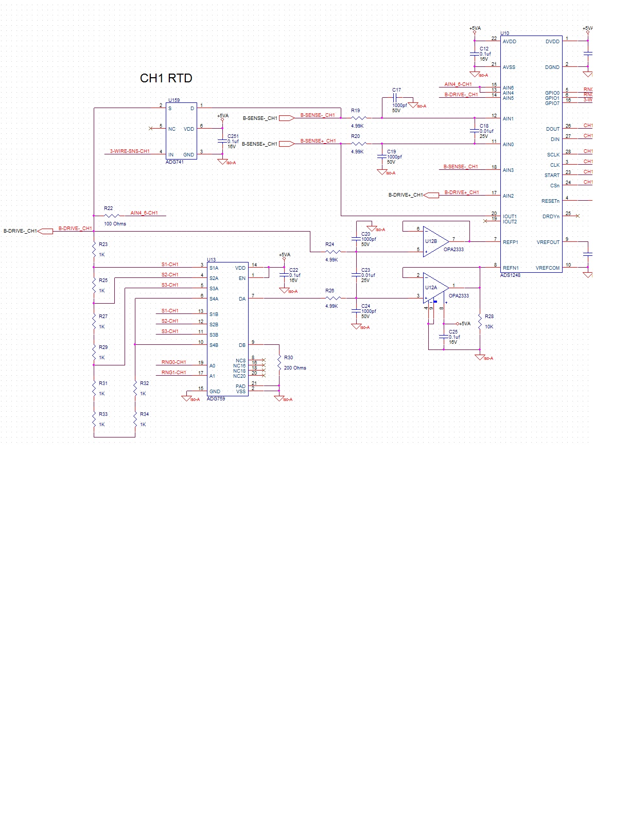
I designed in the low pass filter as described in SBAA201 using Cin = .01uf, Ccm = 1000pf, R = 4.99k. I have an external relay (5ms bounce time) switching in a variety of resistors into a single Ain(Ain0,Ain1) for test purposes. My application is 2 wire mode with 100ua excitation current.

Occasionally I see a significant offset (10ohms) in my reading after a relay switch. If I reapply the relay switch, the offset goes away.

If i remove the filter, I never see this offset phenomenon.

  • Chris,


    I've never used a relay for circuits like this. In general, an analog switch or multiplexer works, without having to use relay drivers.

    What relay are you using (make and model)? Do you have schematic to share?


    Joseph Wu
  • Chris,


    I should also have asked if the offset you are seeing corresponds to a 10Ohm offset caused by the relay (i.e. the relay seems to have a 10 Ohm series resistance. If that's the case, do you see a 1mV drop across the relay? This would be the 100uA current reacting with the relay itself.


    Joseph Wu
  • A relay is the preferred approach when switching RTDs because a FET will have an Rds that varies over temperature. This would result in large measurement errors. A typical RTD varies 0.5 ohm/ deg C. So a 3 ohm Rds variation would result in 6 deg C error.

    The relay is external to this circuit and is in series with a resistor connected between the sense+ and sense- below.

    ADG741 is a switch allowing Iout1 when in 2 wire mode. The Rds on for this switch is calibrated out in firmware.

  • I can replicate this phenomenon without a relay by simply connecting a resistor via banana plugs between sense+ and sense-, and rapidly connecting/disconnecting one end until the offset is latched. Once the offset is latched, if I disconnect the plug and reconnect the plug, the offset is removed. Increasing the cap values seems to help, and totally removing them solves the problem. But I need filtering.
  • Chris,


    If you reduce the size of the input resistors, is the error reduced as well? I would see if the reducing the resistors to about 1k reduces the effect. If increasing the cap values help, does the error decrease linearly?

    What PGA and data rate are you using? How much does the effect change when you change these settings. When you see these errors, is this for a two-wire measurement? How is the current routed?

    How big is this error? I'd asked this before, but I need to know what value this error is in voltage. You mentioned that it was a 10Ohm offset, but is this 1mV Are you getting 10Ohms with 100uA of excitation current? I need to know more about the voltages that you have in your setup (the voltage of the reference, size of the voltage measurement, and the size of the relative error). If it's a large error, you may be able to make some measurements of the input and reference and make sure the ADC is giving back what you think it should.

    Is the error in your measurement transient? When I ask that, I mean does it just take extra time to settle, or do all subsequent readings have the same error? Could this error come from a similar change in the reference? If you're instantaneously plugging in the resistor or RTD into the circuit, it's constantly jerking around the inputs of the OPA2333 so that it might be overdriving it and may require some recovery time.

    If you change the excitation current, does the error scale linearly with the measurement?

    I'm still not sure about the methodology of your measurement, there's a lot of extraneous circuitry in this schematic. It might help if you explained the measurement methodology and how the inputs and reference are setup.


    Joseph Wu
  • Joseph,

    My design uses the Ratiometric approach as described in SBAA201. PGA=8, 5sps, 100ua. The resistor I am measuring is 100 ohms. The reference resistor is 8k, therefore Vref = 800mv.   In 2 wire mode the excitation current is routed from Iout1 thru the sense+, thru the external resistor, thru the sense-, thru the ADG741 switch and finally thru the 8k reference resistor. I translate the ADC voltage reading to resistance in firmware using ohms law. The error occurs due to switching the resistor in and out at some arbitrary rate and it is significant and not fixed(approx 10-20 ohms), and not transient (it is a latched error). The error is removed when I  switch 1 more time. I suspect something is charging to an incorrect value and not discharging. I have changed the filter to use R=15k, Ccm=.01uf, Cdiff=0.1uf and I have not been able to duplicate the problem. So this looks like the solution, although I do not fully understand why. Maybe the larger RC time constant does not allow the switching to charge up the filter caps? Maybe the chopper circuit internal to the ADC is not compatible with the filter? Maybe the OPA2333 are not necessary?

  • Chris,


    Is there a reason you're using such a low current for your measurement? I would have used the 1mA setting for the 100 Ohms. That way, you've got at least a 100mV measurement instead of a 10mV measurement. You'd have to change out the reference resistors too, but it still works.

    Also, if there is a problem in the measurement, any extra resistance looks larger and the error becomes greater - making it a bit easier to find where it comes from. Then it just comes down to making multimeter measurements around the input and reference. (A 3458A works great, a 34401A probably works too).

    I would have used lower value filter resistors (near 1k). I've seen problems with filter resistors >10k where small inputs may give a non-linear result near 0V. The input sampling with such a large series resistance can be disrupted with small inputs.

    I would not have used the OPA2333 for reference buffering. Even though the offset is small and it would give a higher input impedance, the problem would be that it has a low bandwidth. It wouldn't be good for dynamically charging the reference sampling capacitor, which happens on the modulator clock interval. In my mind it's extra devices that don't give you much benefit.

    I can't imagine that the chopper circuit would be incompatible with the filter. I've seen lots of variants of filters, and none that give an intermittent error like this.


    Joseph Wu
  • Joseph,

    According to the datasheet, performance is significantly improved with higher PGA gain settings. That is why I chose a low current. This is an RTD application where resistance can range from 18 - 3900 ohms. 100 ohms is just a test during development.

    A lower filter resistance causes the RC time constant to shorten, and the problem becomes worse (more offset latched errors)..

    A longer time constant solved the problem. The app note indicates that 20k ohms should be the max. I use 15k.

  • Chris,


    It's true that the noise improves as the gain goes up, but you need to make sure that the signal is as large as possible to get the best resolution. As the gain gets larger, the input referred noise gets smaller, but you still may lose resolution.

    I don't have any numbers for a reference of 0.8V which is what you have in your setup, but let me take a basic example based on numbers that are in the datasheet.

    Let's start with 600 Ohms as an example measurement, with 20.48k as the reference resistor, and 100uA as the excitation current. This gives a reference of 2.048V and an input signal of 60mV. With this setup, you could put the PGA at 32 without overranging the input.

    If you look at Table 3 in the datasheet, that would give a noise of about 0.32uVp-p of noise in the measurement. Comparing the signal of 60mV to 0.32uVp-p that's a signal to noise of about 105dB

    Moving on to a second example, let's measure the same 600 Ohms with a 1.5 mA excitation current. That would give a signal of 900mV to measure. With that signal, you could use a PGA of 2. Going back to Table 3, that would give a noise of 4.17uVp-p. Comparing 900mV to 4.17uVp-p you would get a signal to noise ratio of 107dB.

    That's only a small improvement, but it is better when you start with a larger signal. The real benefit is that for the rest of your system with a larger signal, you have a higher noise floor to work with for a similar resolution. That is, the amount of noise in your system only has to be lower that the 4uV instead of 0.32uV.

    Again, it's just a basic explanation using idealized conditions, but I did want to point it out. I would also note that with 3900ohms as the max input, you could only go so far with the the size of the excitation current. The point would be that you want maximize the signal. One potential drawback with a larger excitation current is that there is potential for self-heating in the RTD element.

    On a side note I would have used 10k as a max, but if it's in the datasheet, it means someone has looked at it with some confidence. I'd still check to make sure that the performance is what you want.


    Joseph Wu
  • Joseph,

    I just came across SBAA111. See section 10 on input filter concerns. Could this be what I am experiencing?

  • Chris,


    I mentioned using series input resistors less than 10k because of similar reasons described in SBAA111 (although I don't think I'd seen that applications note in years). The input filter can often change the settling on the input sampling capacitors. However with the ADS1248, there is an active input buffer/PGA, so the problems is not as significant. You will still have some parasitic capacitance due to the input buffer chopping, but it's likely that would be seen as a tiny gain error.

    However, I don't really think that's what you're problem is. What you're seeing with the intermittent offset seems like a problem of over-ranging and failing to properly recover. I'm still suspicious of the reference buffering. You could try making measurements with a variety of input amplitudes. If the error is proportional to the input signal, it's likely that the error comes from the reference somewhere, while if the error is constant with the input signal, then the error comes from the input side.


    Joseph Wu