Other Parts Discussed in Thread: ADS1299
I build an circuit board with the great help of EEG Front-End Performance Demonstration Kit and the recommendations on ADS1299 Manual .
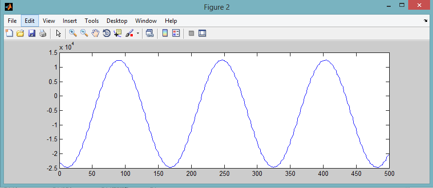
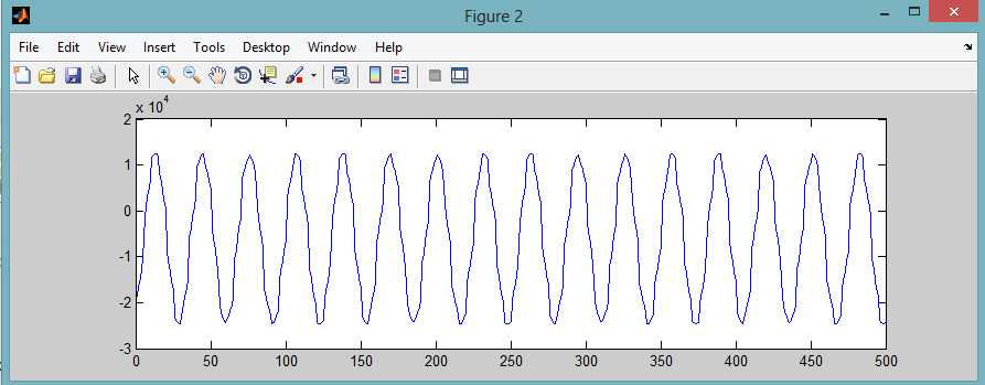
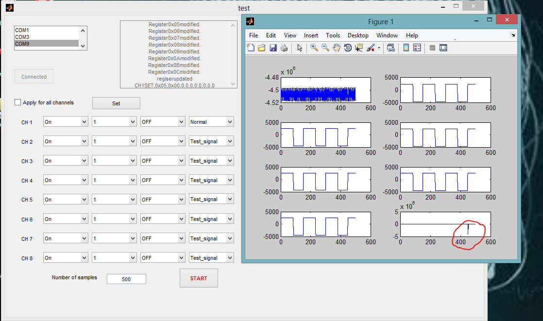
I can read and write registers correctly to the chip and it works fine with the internally generated test signal as the image bellow.

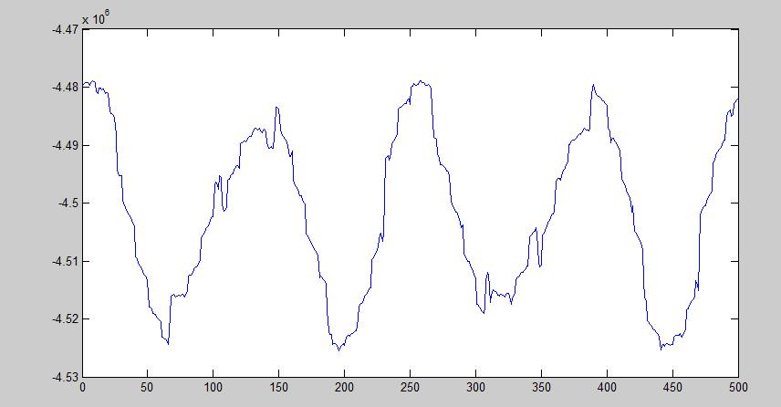
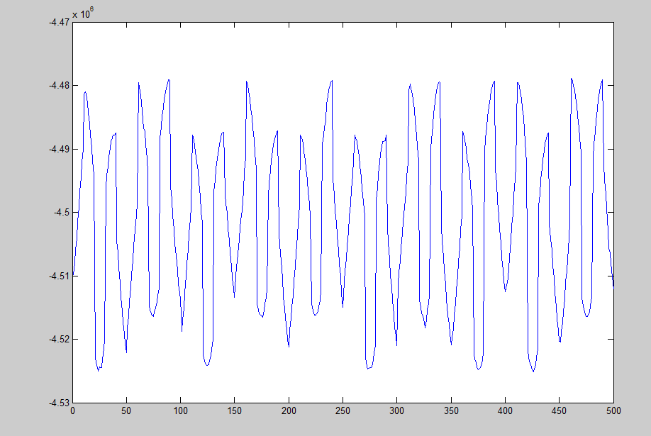
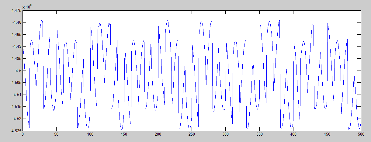
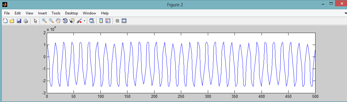
But when I set a channel to normal electrode mode the problem starts.. Here I set CHANNEL 1 to normal elactrode mode with Gain 1 and others are in test signal mode. But there is an corrupted value in CHANNEL 8 which repeat every time as follows
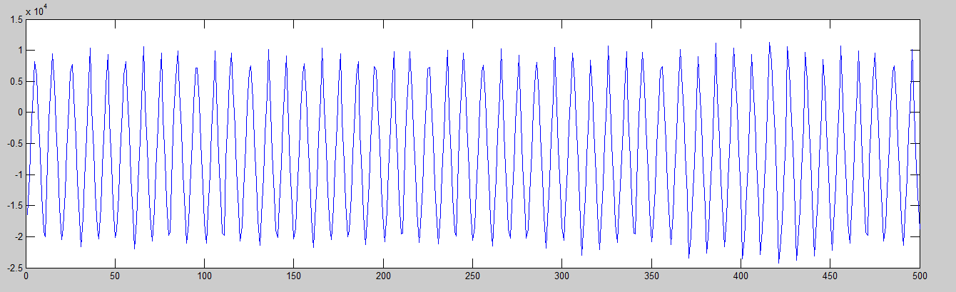
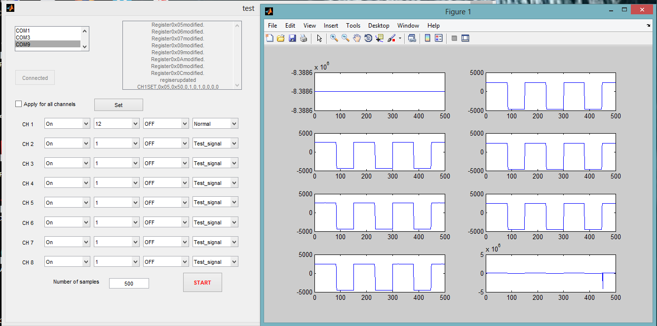
Then I change the gain value of the CH1 1 to 12 problem remain same and another problem started at gain =12... the output CH 1 becomes at its lowest value (800000h). this happens for Gain = 12 ,24
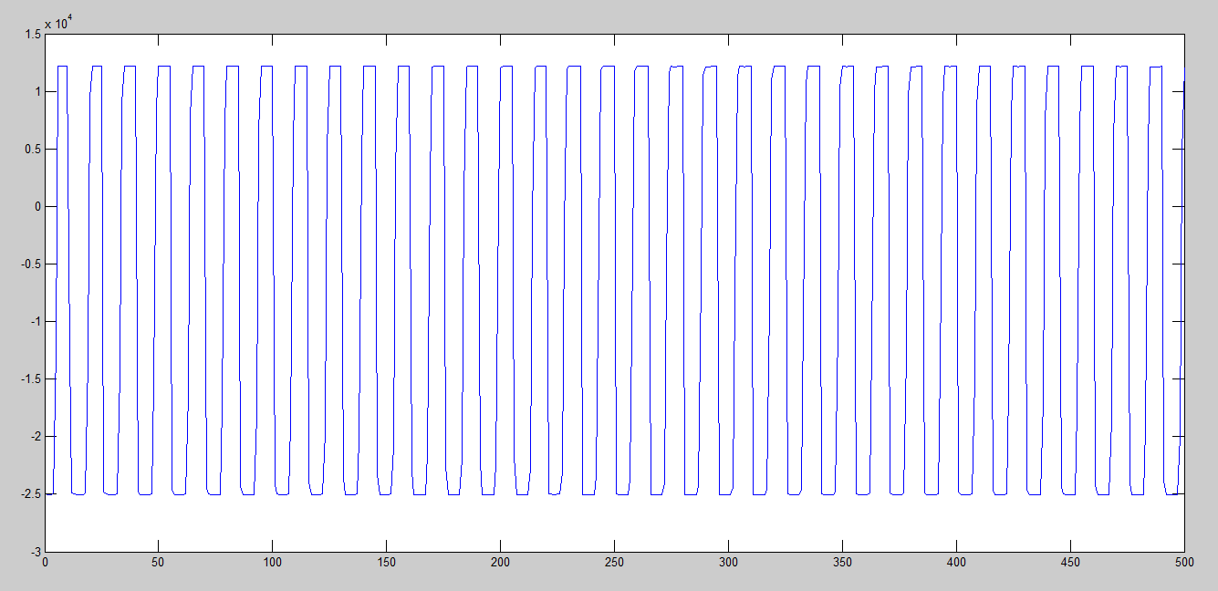
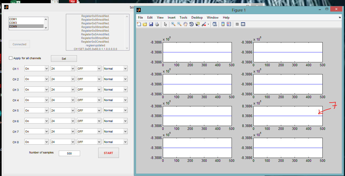
Then I Change all the Cannels to Normal Electrode mode and Gain = 24.. all the sample values of the channels gets 800000H except CHANNEL 7 . CHANNEL 7 gets the Maximum binary value(7FFFFFH)...
I have Enable the internal reference and Clock..
Please Help me to solve this problem