This thread has been locked.

If you have a related question, please click the "Ask a related question" button in the top right corner. The newly created question will be automatically linked to this question.

Calculating Resistance with ADS1248

Other Parts Discussed in Thread: ADS1248

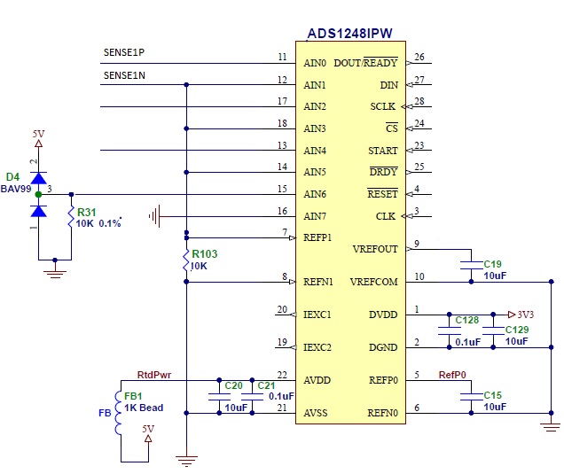
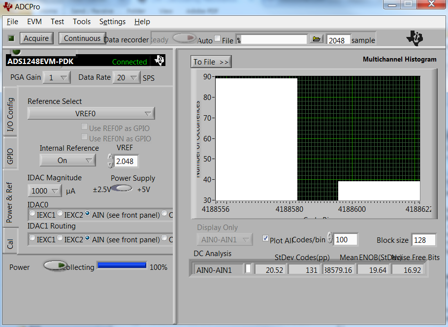
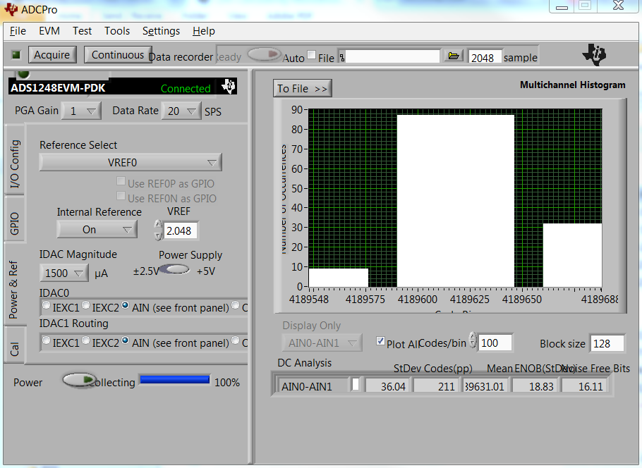
I'm trying to do a resistance measurement between AIN0 and AIN1 of the ADS1248, but the numbers aren't adding up...

I use IDAC Current Output 1 to drive 1ma to AIN0

(

   IDAC 0 Reg 0xA = 6; // 1ma

   IDAC 1 Reg 0xB = ( 0 << 4) ;  // AIN0

)

but I read 0x7FFFFF for all but very small resistor values..   I do see 1V across R103 (10K), suggesting that the 1ma constant current source is working.

How can I calculate the resistance across AIN0 & AIN1 ?

  • Blipton,


    Are you sure that you are using 1mA for the excitation current? 1mA x 10kΩ is 10V. It would make more sense if you are using a 100uA excitation current.

    First, about the schematic. I would remove FB1 and replace it with a short. The inductance in the supply line could cause you some errors. With the digital line (and even with the analog line) there are switching currents, that will cause voltage spikes with the L(di/dt).

    For your measurement, make sure that all of your excitation current flows through the resistor you are measuring (across SENSE1P and SENSE1N) and the reference resistor (R103). Then, make sure that you are using REF1 as the reference input and that you have the internal reference on. The internal reference needs to be on to use the excitation current source. Then make sure that there isn't anything else in series with the inputs that might be adding to the measurement signal. For example, an input filter is often added to the front end of the input at AIN0 and AIN1. If the excitation current is driven from AIN0, then the filter resistance on AIN0 becomes part of the measurement error.

    Once you verify that the proper current is going through the measured resistor and the reference resistor, then it is easy to verify the resistor value. Since the ADC output code is a measurement of the ratio between the input voltage and the reference voltage you get this relationship:

    Measured resistor = (reference resistor x output code)/2^23

    Remember that if you want a stable measurement, you need a stable resistor. Typically the reference resistor is high accuracy and low drift.


    Joseph Wu
  • Ok, removed FB1 with a short, I also verified there is nothing else connected to AIN0 & AIN1 except for a 1k resister (measured).

    The reference resistor is currently 2K (measured). I've experimented with different values, but the schematic hasn't kept up...

    At power-on, I initialize the chip with:
    Reg Addr 0x00 = 1;
    Reg Addr 0x01 - 0x6 = 0;
    Reg Addr 0x0A = 0x6
    Reg Addr 0x0B = 0x9
    Reg Addr 0x0C = 0
    Reg Addr 0x0D = 0
    Reg Addr 0x0E = 0xa5

    And every time I do a reading on the AIN0 channel, I write:
    IDAC Reg Addr 0x0B = 0;
    Set Start High and Wait for Data Ready to Go Low
    Send Command 0x12 and Read Back 3 bytes

    The output code reading varies ( 0x601bb2 - 0x606060), but still doesn't compute: ~1500 ohms instead of 1000 ohms

    What's interesting, after setting the IDAC Register, and before sending the 0x12 read command, I see about 3V across the 2k. Seems like the output current is not getting set correctly?
  • Blipton,


    I have a couple of comments. First, make sure that when you write to the register, the START pin is high. I don't think that you can write to the registers if the START pin is low, since the device is in a powered-down state.

    Second, check your configuration. In the last post you say that Reg Addr 0x01 - 0x6 = 0. I don't think is the setup you want. For the MUX1 register, you should have something like 28h. You want the internal reference to be on, which will enable the IDAC currents. Second, you want to set the reference to use REF1, instead of REF0 or the internal reference.

    I would read back the registers to make sure that the values are correct. This will also tell you that your communications with the device are valid.


    Joseph Wu
  • Blipton,


    Just to check, could you please also set the data rate to 1000SPS? I'd like to verify that there isn't a problem in the sampling.


    Joseph Wu
  • Thanks,

    The debugger was showing that MUX1 was '0', but it was formatting it in ascii.. the actual setting read for reg 2 is 0x30 (i.e. Internal Ref On, using On-Board reference). I changed this to 0x28 (i.e. Internal Ref On, using REF1) and increased the sampling rate to 1000 (from 5).

    Now the output reading varies from 0x408df9-0x40a3ed , which computes much better (~1010 ohms for the same 1000 ohm source), but there seems to always be positive 10-30 ohm offset no matter what resistor value I use across AIN0/AIN1.

    Also, when I read the voltage across the 2k ref resistor, it still shows 3V. I removed the resistor off the board to make sure it measures 2k by itself and it does, so not sure if this anomaly is related to the offset in the reading?

  • Blipton,

    I suspect that you're writing the wrong value to the IDAC0 register and setting the IDAC current to 1.5mA. Even if this is set incorrectly (compared to 1mA), it will still give you the correct result for the ADC code.

    As an experiment, I set up the ADS1248EVM to test this out. I have 1k resistor from AIN0 to AIN1, with IDAC0 set to AIN0. Instead of REF1, I put 2k across REF0, and connect the negative end to AVSS, and the positive end to AIN2 so that the current is shunted through the reference resistor. I used REF0 instead of REF1 so I don't have to de-solder resistors to disconnect the REF5020 on my board. IDAC1 is set to AIN2, which is an unused channel. The internal reference is set on so that the IDACs are operational.

    Because there are some series filter resistances on the inputs, I short out the filter resistor on AIN0. If I hadn't done this, the IDAC current would react to the series resistance to give some added error.

    With a 1mA excitation current, 1.001V is seen across the 1k resistor, and 2.005V is seen across the 2k resistor.

    With a 1.5mA excitation current, 1.406V is seen across the 1k resistor, and 2.816V is seen across the 2k resistor. Note that this is a bit lower than the full 1.5mA of excitation current because the current source starts to lose compliance to the postitive rail. Even though current starts to droop, it generally shouldn't affect the measurement because the same current goes through both the 1k and 2k resistors.

    With the 1mA excitation current, the measurement comes out to 4188579, with the 1.5mA excitation current, the measurement comes out to 4189631. In the first measurement, that comes to 998.6Ω, for the second, that comes to 998.9Ω. Even though it should be the same, there are a few differences in the circuit that may account for the difference in codes. First, if you make the same measurement remember to remove the multimeter first. This adds to the error since this gives an added leakage for the excitation current. Second, since the inputs are different there may be a different input current (imagine that the input has a equivalent input impedance, and I wasn't able to short the other series impedance on AIN1). Also, the inputs have different common-mode points, which may also have a different common mode error.

    Regardless, it's certainly possible to get a result that makes sense. I'm sure that there's a simple explanation why your reference resistor is showing a high voltage.

    Joseph Wu

  • Thanks!  I noticed that the voltage across the resistors changes, so I think the anomaly is due to the switching of the IDAC Source for each Channel.   For example, across the 1K sense resistor I see 1V on the DMM momentarily, then it ramps up to about 1.6V and repeats.   Similarly, the 2k Ref varies from 2V to 3V.    

    Since the numbers are in the ballpark, I think the offset can be cal'd out.

    Thanks for the help!

    REG 0x0 : 0x1

    REG 0x1 : 0x0
    REG 0x2 : 0xa8
    REG 0x3 : 0x0
    REG 0x4 : 0x0
    REG 0x5 : 0x0
    REG 0x6 : 0x0
    REG 0x7 : 0x80
    REG 0x8 : 0x17
    REG 0x9 : 0x40
    REG 0xa : 0x96
    REG 0xb : 0x0
    REG 0xc : 0x0
    REG 0xd : 0x0

  • Blipton,


    If you're changing IDACs through different channels, the change should be immediate. The only reason there may be a delay would be due to circuitry outside of the ADS1248. If you have large filtering capacitors, and you swap channels, then it may take extra time to fill the capacitance to the final value.

    Regardless, if you are getting values close to what you expect, you're probably on the right track. If you have any more questions, please feel free to post back.


    Joseph Wu