
- Ask a related questionWhat is a related question?A related question is a question created from another question. When the related question is created, it will be automatically linked to the original question.
My current project requires that I capture analog inputs up to 40kHz bandwidth from 4 sources simultaneously. I'm using the TLC1518 as my ADC and I seem to have hit an impasse with this chip.
At the moment, my setup includes a microcontroller (Freescale MK20DX256VLH7) communicating with the TLC1518 using SPI.
The pin connections of the TLC1518 are:
The SCLK, CS, SDO, and SDI pins of the ADC are connected to the SCLK, CS, MISO, and MOSI pins of the microcontroller.
I wish to utilize the following settings on the TLC1518:
Because of this, I realize that I need to configure the TLC by sending in the code 0xA004. At startup I have the microcontroller send the sequence
0xA000 -> 0xA004 -> 0x9000
At first, I followed this with sampling commands 0x1000 -> 0x2000 -> 0x3000 -> 0x4000, but since this always gave an output of zero, I switched to sending in my startup sequence continuously.
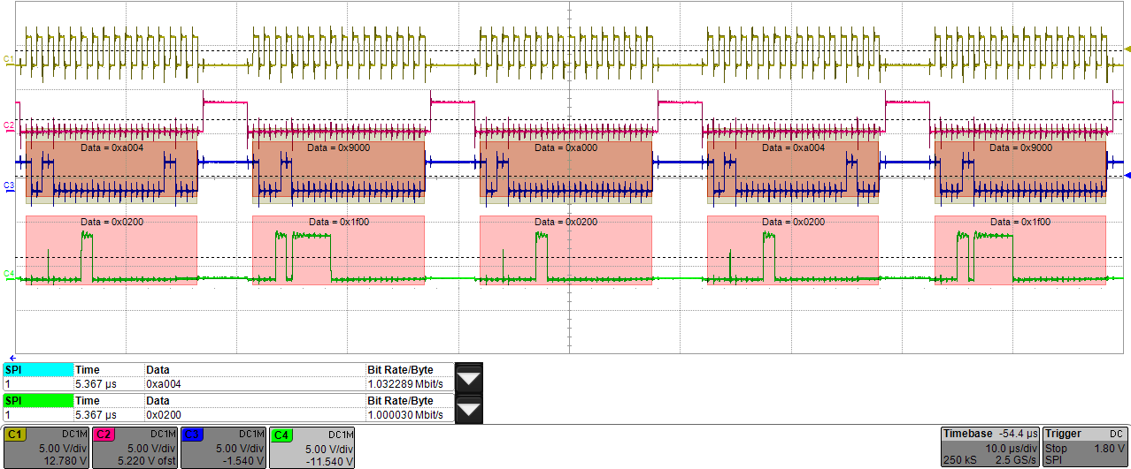
The following images show my output. The yellow wave is SCLK, the pink in CS, the blue is SDI, and the green is SDO. I temporarily set SCLK frequency to a low value of 1 MHz when debugging so that sampling occurs at about 50 kHz. I was getting an identical result at higher frequencies. The SPI format I'm using is CPOL = 0 and CPHA = 0.
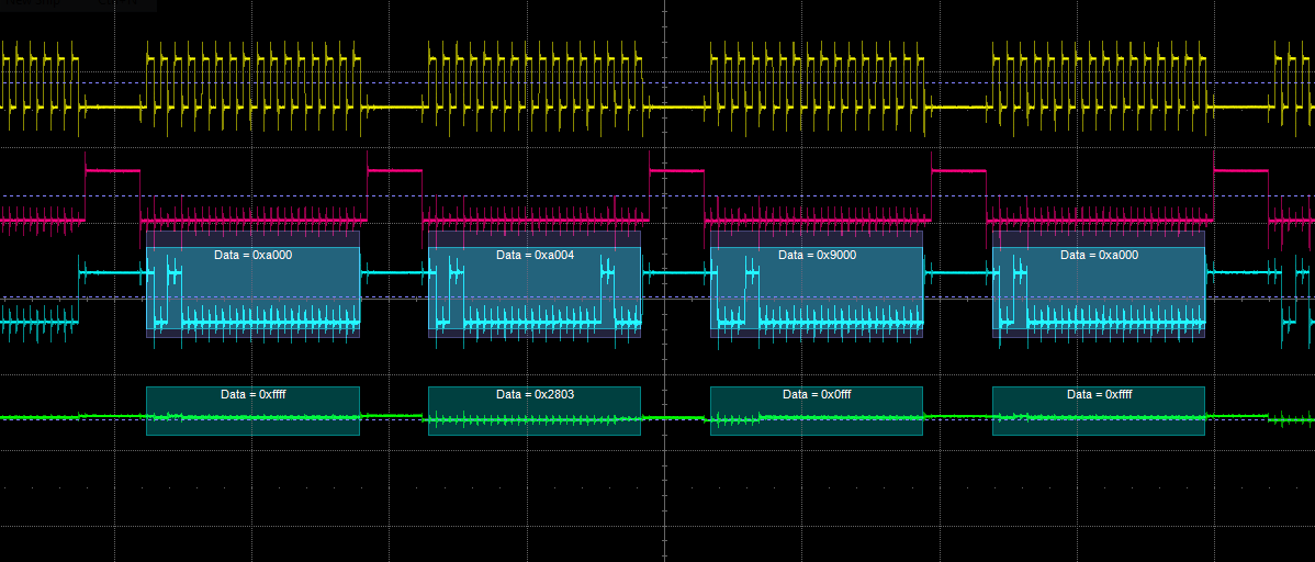
It seems that the TLC is trying to do something in response to the microcontroller input (and my oscilloscope is picking up on that), but these voltages are way too low to be read. Even if they were, they do not make any sense whatsoever.
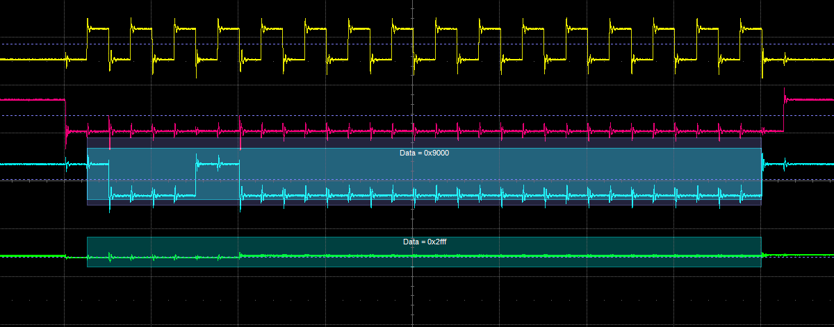
As a final note, I accidentally discovered that resetting the power on the ADC produces non-zero output. Here is an image (I apologize for the different format):
The output data above (green) changes in a seemingly random pattern whenever I reset the TLC.
What is causing this? Is my chip defunct?
Thanks


