This thread has been locked.

If you have a related question, please click the "Ask a related question" button in the top right corner. The newly created question will be automatically linked to this question.

Helping to select correct ADC EVMs

Other Parts Discussed in Thread: LMH5401, TSW12J54EVM, TSW14J50EVM, TIDA-00431, TINA-TI

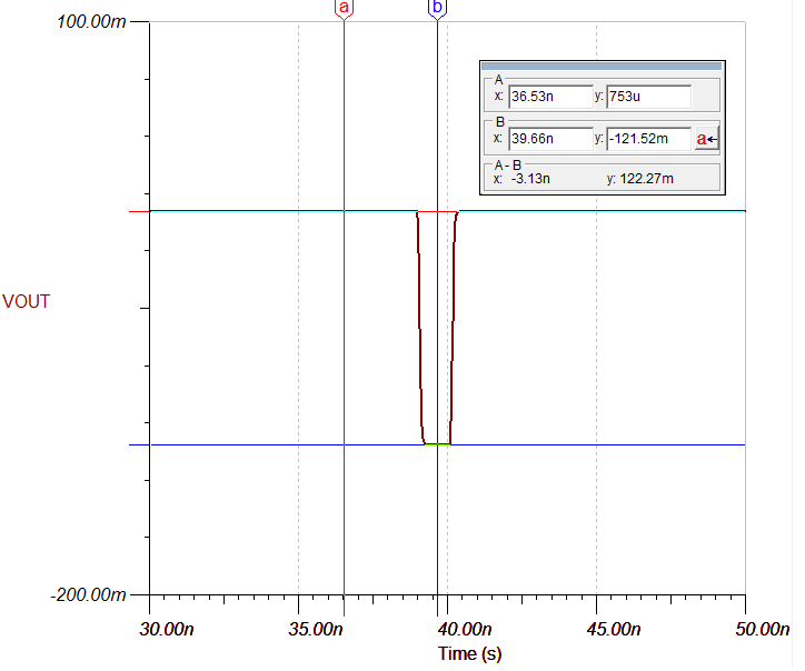
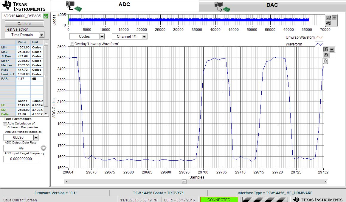
I need help to determine the EVM board and configuration for my data acquisition project -- I need to acquire output from a photo multiplier tube. The signal will be pulses with 2-3ns pulses duration. The repetition rate will be <10KHz.

I hope to use EVM for the project. One issue I saw from many EVMs is that they have a transformer coupling therefore limiting the lower band to 3-400MHz. In my case, I really need to full bandwidth to obtain a sharp pulses...

Any suggestion will be greatly appreciated.

Regards, Bing

  • Hi Bing

    You could consider the TSW12J54EVM. It has an LMH5401 amplifier front end that can be configured for a single ended DC coupled input, with 50 ohm input impedance. This will provide signal bandwidth coverage from DC to 2 GHz.

    Best regards,

    Jim B

  • Jim,

    Thanks a lot! Does this board requires a "data capture" board to have access to the data from a PC?

    Best regards, Bing
  • Hi Bing

    Yes, it will require the TSW14J56EVM for data capture. This will enable all sample rates and modes of the on-board ADC. The TSW14J50EVM can also be used, but that will limit the maximum sample rate allowed.

    The High Speed Data Converter Pro software (http://www.ti.com/tool/dataconverterpro-sw) will be used to configure and control the capture board, and to display, analyze and save the data.

    Best regards,

    Jim B

  • Jim,

    Sorry I have a couple more questions...

    1) Is there a way to trigger the data acquisition on TSW12J54EVM?

    2) If there a way directly pipe data into Matlab using the High Speed Data Converter Pro software?

    Thanks again.

    Jim Brinkhurst84999 said:

    Hi Bing

    Yes, it will require the TSW14J56EVM for data capture. This will enable all sample rates and modes of the on-board ADC. The TSW14J50EVM can also be used, but that will limit the maximum sample rate allowed.

    The High Speed Data Converter Pro software (http://www.ti.com/tool/dataconverterpro-sw) will be used to configure and control the capture board, and to display, analyze and save the data.

    Best regards,

    Jim B

  • I have a couple more questions regarding the TSW14J56 EVM. In the user manual it specifies the default trigger input voltage is 1.8V, however the trigger output device in my system will have a TTL signal at 3.3V level.

    I wonder how to configure TSW14J56EVM to take a 3.3V trigger input? I can't seem to find any information in the user manual.

    Thanks again, Bing

  • Hi Bing

    The trigger input has some adjustment capability, but cannot be adjusted high enough to tolerate a 3.3V signal.

    I recommend adding a level shifter or resistive divider in between your trigger source and the TSW14J56EVM trigger input to reduce the high level voltage to a maximum of 1.8V.

    Best regards,

    Jim B

  • Jim,

    A related question -- I actually have to trigger two devices, while TSW14J56EVM takes 1.8V, the other has a 5v 50ohm input... I know this might be a bit out of the scope, but can you suggest a solution to accommodate both (an existing TI EVM board would be even better...)?

    Thanks, Bing
  • Hi Bing

    My thought is to use a dual amplifier to buffer your 3.3V ttl signal to the two different loads.

    Something like this EVM might work: http://www.ti.com/tool/alm2402q1evm

    You could configure one channel with enough gain to drive the 5V 50ohm load and the other channel with some attenuation in the input termination resistors followed by unity gain to give you a 0 to 1.8V swing on that output.

    If you look around in the power amplifier area (needed to drive the 50 ohm load) you may find something ever better suited. Here is the search I had started with: http://www.ti.com/lsds/ti/amplifiers/op-amps/power-op-amps-products.page#p1max=0.0004;0.5

    Best regards,

    Jim B

  • Jim, we have set up the TSW14J56EVM and TSW12J54EVM for data collection. However, one thing we are struggling with (after getting over a bug in the high speed data converter software), is that there is a coupling from the trigger signal onto the signal line, which we don't see on the scope.

    I wonder if you may have any suggestions how to mitigate such issue?

    Thanks, Bing
  • You can try setting the Trigger Delay in the Trigger menu. This will delay the start of data capture after the trigger has occurred. See the HSDC Pro users guide Table 1 for details.

    Ken.
  • Ken, thanks. I am not sure trigger delay can help. I am including some trace capture from the scope and the screen dump of the GUI. As you can see the much significant undershoot in the GUI screen capture...

    What's your thought on what might cause this?

    Thanks again for your help.noise_issue.docx

  • Bing,

    Have you tried running the trigger without the input from your system? Maybe terminating the input of the ADC EVM? This will show you if there is a trigger related issue which should occur at the same place with every trigger/capture.

    Also if you adjust the trigger to pulse skew, the undershoot should track as well.

    If the undershoot only occurs with the signal pulse all the time, I'm more inclined to think that this is due to the pulse response of the amplifier driving the ADC. You can also try just sending a narrow pulse (from a pulse generator) into the system and see what the response looks like. If the pulse response is causing the undershoot we may need some help from the amplifier team to optimize this circuit.

    Ken.
  • Ken,

    What we noticed is that if we use a longer pulse (20ns, 4.5ns rise/fall time, 0.2v) from the signal generator, we did not notice any undershoot (our signal generator can't generate shorter pulses). However when we switch to the 2ns laser pulse we would see this undershoot (see attached doc).

    It is almost as if the ADC board does not have sufficient bandwidth. BTW, is it possible to provide the schematic of the ADC board TSW12J54EVM? Also, can you please help to refer to the amplifier team if you feel they might help?

    Thanks again,

    Regards, Bingsignal.docx

  • Bing,

    I'm thinking there is a pulse response issue with the signal path. I will have the amp team have a look at this post.

    For the design files, please see this link below for the TI Design - TIDA-00431
    www.ti.com/.../TIDA-00431

    Ken.
  • Ken, Thanks.

    At mean time, I have another issue to consult you -- the way I will use the system is to use a TI DMD evaluation system to generate a 5Khz trigger. So every time there is a trigger, I hope to use the ADC board to record a time series data (Photo-multiplier tube response). I hope to record all the data...

    Can you provide a guidance how to do that. I hoped to directly extract data in Matlab... But if that's not possible, then if I can save the data into a file and process at later time is ok too...

    Thanks again.

  • Bing,

    Looking at the pulse response data you provided for the 2ns laser pulse, it looks like the input is not properly terminated rather than the board not having sufficient bandwidth.

    Is it possible that you can provide a rough block diagram of your test setup? Are you driving only one of the board inputs in single-ended configuration while the other input is terminated externally with 50-ohms?

    Best Regards,

    Rohit

  • Bing,

    Concerning the 5kHz trigger, we can trigger and capture data, but you will not be able to transfer the data quickly enough to capture data on a repetitive manner. The system was not designed to do this kind of fast capture evaluation.

    Ken.
  • Ken,

    Is it possible to capture/store a batch of runs (i.e., maybe data from ~200 triggers) on the system and then offload to the PC in batch mode? I can also slow down the trigger from 5KHz to 1KHz.

    If you have any other suggestions, please let me know...

    Thanks, Bing

  • Bing,

    We don't have a means to officially do this - the firmware was not designed to do this.

    Ken
  • Rohit,

    Here is a connection diagram:

    The PMT is a current source, so we used a variable terminator from Thorlabs (VT1). I think one issue is that the terminator may have a bandwidth limit of 300MHz.  Do you have any suggestion what to use?

    Thanks.

  • Ken, that's great. My email is bouyang@fau.edu. Thanks again.
  • Bing,

    Would it be possible for you to please re-attach the connection diagram as it looks like it did not get through.

    I would suggest using an SMA male 50-ohm termination like the Minicircuits: MCL ANNE-50X+.

    Best Regards,
    Rohit
  • Rohit, Sorry about that. I am resending it again.

  • Bing,

    If you are using the VT1 in series with the PMT current source, then I don't think it is providing the right termination for the TI ADC board. The termination needs to be shunt across the PMT current source to provide proper 50-ohm termination. One way to think about this is that the current source and the shunt termination is a Norton equivalent of the voltage source and series resistor.

    To make this change, you could replace the R168 in the board schematic with 44 ohms instead of the 365 ohms, as shown below on the PMT source input (VIN-). Also, I just wanted to confirm that you should be using a 50-ohm external termination on the un-driven (VIN+) input like the Mini-circuits: MCL ANNE-50X+. I have verified the below setup in TINA-TI simulator and it does not seem to show any undershoot in the pulse response.

    Best Regards,

    Rohit

    Output pulse response:

  • Rohit, Thanks again. One thing is that the VT1 is a parallel 50ohm termination, not a serial terminator, so do you think we will need to change the resistor?

    Thanks, Bing

  • Bing,

    I think you are right that the VT1 is a parallel 50ohm termination, so you will not need to change the resistor. However, I do feel that the VT1 is bandwidth limited to <500MHz which might be responsible for the undershoot in the pulse response. One way to prove this is by eliminating the VT1 from the signal chain by replacing the R168 with 44 ohms and driving the PMT source directly. I think this might give you some clue as to where the undershoot is coming from. 

    Best Regards,

    Rohit 

  • traces1.pptx

    H10720_H10721_TPMO1062E.pdf

    Rohit,

    We modified the board but we still have the same issue with PMT. However we did not have any issue with a 8ns pulse from a signal generator... I am attaching the mod we did and the traces and the PMT spec sheet. I wonder if you can suggest any other possible way to mitigate the problem?

    Thanks, again, Bing

  • Dear Rohit, I wonder if you had a chance to look into my problem more?

    Thanks again, Bing

  • Bing,

    I think the excess undershoot that you are noticing in your data capture might be a result of peaking in the transfer function of the signal path, while converting a single-ended signal to a differential signal. One way to reduce this peaking, is to operate the front-end amplifier at a slightly lesser bandwidth such that the peaking is reduced. 

    I would recommend you to make the following changes to the schematic at the LMH5401 front-end, to reduce the excess undershoot. I was able to capture the data without much undershoot for a 1 ns pulse on the same board you are using.

    Best Regards,

    Rohit

  • Rohit, just want to confirm with you before we make the mod -- you did notice the undershooting for 1ns pulse with the configuration I used?

    Another question -- can you recommend a site to buy those resistors you suggested? Some were difficult to find...
     
    Thanks, Bing

  • Bing,

    Yes, I did see the undershoot for 1ns pulse for the falling edge as you saw in your data capture.

    I think these resistors are standard values available at sites such as digikey or mouser. http://www.digikey.com/product-search/en/resistors/chip-resistor-surface-mount/65769?k=Automotive%20Resistors. If you don't find the values I suggested, then the closer value resistor should also work.

    Best Regards,

    Rohit