Because of the Thanksgiving holiday in the U.S., TI E2E™ design support forum responses may be delayed from November 25 through December 2. Thank you for your patience.

This thread has been locked.

If you have a related question, please click the "Ask a related question" button in the top right corner. The newly created question will be automatically linked to this question.

ADS1258 input circuitry & opamps

Other Parts Discussed in Thread: TLV2774, OPA365, ADS1258, OPA228, OPA376, OPA4350

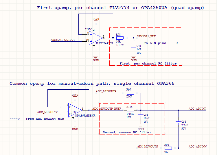
We're using 10 out of the 16 channels of ADS1258 in single-ended mode in an application. (VREF=5V). 4 of these channels have to be measured very accurately, so we plan to pass them through an opamp (TLV2774 or OPA4350UA). Then, for the MUXOUT-ADCIN path, we plan to use another opamp (OPA365, which is referenced in a few places in the ADS1258 datasheet). The rest of the channels other than the four, will only use the OPA365. The circuit looks like below:

Do you see any general problems with this approach?

  • Hi Hakan,

    I'm not sure if the additional buffer prior to the MUX will be of much benefit...Each additional amplifier stage will contribute additional noise, offset and offset drift to your measurement and the offsets of the TLV2774 and OPA365 are fairly high to begin with - though the offset drifts aren't too bad, so you would be able to calibrate out the initial offsets. Still you might consider some lower noise and lower offset alternatives, such as the OPA228 or OPA376.

    How close will your input signals swing to the opamp supply-rails?
    The linear range of the TLV2774 will be about 1 - 4V, so within 1V of the supply rail you will see some non-linearity. The OPA228 and OPA376 will also have some linear range limitations; therefore, if you need the full 0-5V range you might also need to consider providing a larger positive supply rail and a negative supply rail.

    Best Regards,
    Chris

  • Hello,

    1) Part of the reason why we think we need the amplifiers before the MUX is to do the RC filtering of the signal. We can not put the RC filter right at the output of the sensor because the sensor can not drive much of a capacitance, and yet it is very noisy above 3Khz. To filter these with an RC filter, we must first buffer the sensor output and then push the signal through the RC filter.... And, we can't put the filter at the output of the second opamp, becuase, first it would interact with the ADC input impedance, and second, we don't want to filter all 10 channels of the data with the same filter.

    2) We need a quad amp for the first stage due to board space limitations, so we can not use the alternatives you suggested, but, what do you think about the OPA4350 ?

    3) Can you point me to the location in the TLV2774 datasheet where I can find out the limitation that you mentioned (non-linearity above 4V and under 1V) ? I can not locate this information in any of the graphs.

    4) We actually don't need the entire range, we only need 0.5V-4.5V. Can you suggest alternatives based on this?

    5) I also noticed that some of the alternatives you mentioned above have low GBW and Slew rate. Is that not a problem? Generally speaking, are GBW/Slew rate inversely proportional with offset voltage?


    Thank you,

  • Hi Hakan,

    1. Buffering the sensor output prior to the RC filter makes sense!
      1. ...If you weren't MUXing between 10 channels, you would be able to take advantage of the low-bandwidth digital SINC filter at a lower data rate to provide additional noise filtering (then the RC filter would only need to serve as an anti-aliasing filter).

    2. Look for OPA4228 and OPA4376 - Those are the quad versions of those opamps.
      The OPA4350 is certainly a good option because it can drive large capacitive loads, allowing you to use even larger capacitor values in the RC filter. It will also be linear to within 50-200mV of the rail (depending on the output load).


    3. This is not explicitly called out in most op amp datasheets, you'll need to know what to look for in this case...
      1. Recall that an ideal opamp works on the premise of having infinite "open-loop" (i.e. without any feedback) gain. In practice opamps need to have a very large gain to function as an opamp, so I usually look for the "open-loop" gain specification and observe the test conditions under which the gain was measured. Within this range you know that the opamp will provide a large gain, and hence, a linear response. However, if you operate any closer to the rail, there is no guarantee that the opamp will be linear.


    4. Most of our precision op amps (usually start with the prefix "OPA") should be linear within 500mV of the rail.


    5. Are those important specs for your application? Generally GBW/slew rate and Vos/Vos drift are directly related. It does seem like higher GBW opamps tend to have larger offsets, but this is not always the case (e.g. the OPAx228 has a GBW of 33 MHz and a typical offset of 5 uV).

    I hope that helps!

    Best Regards,
    Chris