This thread has been locked.

If you have a related question, please click the "
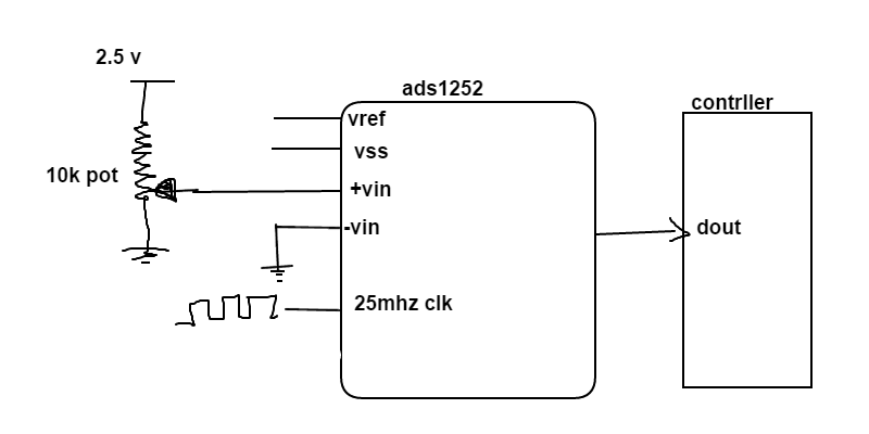
Ask a related question" button in the top right corner. The newly created question will be automatically linked to this question.

I need help with ADS1252 external interace cicruit

Other Parts Discussed in Thread: ADS7040, ADS1118, ADS1120, ADS1252

I don't have analog input so i made Potenio meter as variable input,if this circuit is not working I need suggestion,

  • Hi Nanu,

    Welcome to the TI E2E Forums.

    Is your goal to use the potentiometer as a user control to part of a larger system?
    You could measure the potentiometer this way; however, you probably wouldn't need to use a 24-bit ADC for this type of measurement. I would suggest a much cheaper solution, something like the ADS7040.

    Also, keep in mind that directly connecting the pot to the ADC can have a gain error (due to the resistor divider of the pot + ADC). For more accuracy, you would want to buffer the pot's output voltage; however, for a very coarse measurement you may not be concerned with this gain error. Some ADC's, like the ADS1120 or ADS1118 have a built-in buffer and would allow you to connect the pot directly to the ADC, without the need for an additional buffer.

    Best Regards,
    Chris 

  • Hi Christopher Hall,
    Thanks for your sugestion,whta is the input volatge for vss,and veref?
  • Hi Nanu,

    The ADS1252 does not have an "AVSS" pin, only a "GND" pin which connects to a common ground.

    .Usually when you see "AVSS", the ADC allows for a bipolar supply (+/- 2.5 V, for example). However, the ADS1252 only takes a unipolar (0 to 5V) supply.

    Vref may be anywhere in the range of 0.5 V to AVDD (i.e. 5 V).


    Best Regards,
    Chris

  • 1. 384*CLK   [what is  384?]

  • Hi Nanu,

    nanu alla said:
    1. 384*CLK   [what is  384?]

    I believe you are referring to "tDRDY" from Table II, is that correct? This is the conversion period time (i.e. the inverse of the data rate). The ADS1252's data rate is determined by the external "CLK" frequency, as shown in Table I.


    nanu alla said:
    2.Is it Compulsory 24 SCLK to get 24 bit DOUT?,or also possible by making SCLK High after DRDY operation?

    Yes, 24 SCLK's are required to clock out the data. If SCLK is not toggled then the ADS1252 will not output any data on SCLK. Holding SCLK high for a certain number of conversion periods with either synchronize ADC conversions (when using multiple ADCs) or will put the device in power-down mode.


    Best Regards,
    Chris