Other Parts Discussed in Thread: AMC1304L25
In order to get the data coming from the ADC we need to implement a Sinc3 filter.
//////////////////////////////////////////////////////////////////////////////////
// Company:
// Engineer:
//
// Create Date:    15:37:12 10/26/2016
// Design Name:
// Module Name:    sinc3_verilog
// Project Name:
// Target Devices:
// Tool versions:
// Description:
//
// Dependencies:
//
// Revision:
// Revision 0.01 - File Created
// Additional Comments:
//
//////////////////////////////////////////////////////////////////////////////////
module dec256sinc24b
(
	input mclk1, /* used to clk filter */
	input reset, /* used to reset filter */
	input mdata1, /* input data to be filtered
*/
	output reg [15:0] DATA, /* filtered output
*/
	output reg data_en,
	input [15:0] dec_rate
);


/* Data is read on positive clk edge */
	reg [36:0] ip_data1;
	reg [36:0] acc1;
	reg [36:0] acc2;
	reg [36:0] acc3;
	reg [36:0] acc3_d2;
	reg [36:0] diff1;
	reg [36:0] diff2;
	reg [36:0] diff3;
	reg [36:0] diff1_d;
	reg [36:0] diff2_d;
	reg [15:0] word_count;
	reg word_clk;
	reg enable;
/*Perform the Sinc action*/
always @ (mdata1)
	if(mdata1==0)
		ip_data1 <= 37'd0;
/* change 0 to a -1 for twos
complement */
	else
		ip_data1 <= 37'd1;
/*Accumulator (Integrator)
Perform the accumulation (IIR) at the speed
of the modulator.
Z = one sample delay MCLKOUT = modulators
conversion bit rate */
always @ (negedge mclk1, posedge reset)
	begin
	if (reset)
		begin
/* initialize acc registers on reset
*/
		acc1 <= 37'd0;
		acc2 <= 37'd0;
		acc3 <= 37'd0;
		end
	else
		begin
/*perform accumulation process */
		acc1 <= acc1 + ip_data1;
		acc2 <= acc2 + acc1;
		acc3 <= acc3 + acc2;
		end
	end
/*decimation stage (MCLKOUT/WORD_CLK) */
always @ (posedge mclk1, posedge reset)
	begin
	if (reset)
		word_count <= 16'd0;
	else
		begin
		if ( word_count == dec_rate - 1)
			word_count <= 16'd0;
		else
			word_count <= word_count + 16'b1;
		end
	end

always @ ( posedge mclk1, posedge reset )
begin
	if ( reset )
		word_clk <= 1'b0;
	else
		begin
		if ( word_count == dec_rate/2 - 1 )
			word_clk <= 1'b1;
		else if ( word_count == dec_rate - 1 )
			word_clk <= 1'b0;
		end
	end

/*Differentiator (including decimation
stage)
Perform the differentiation stage (FIR) at a
lower speed.
Z = one sample delay WORD_CLK = output word
rate */

always @ (posedge word_clk, posedge reset)
begin
	if(reset)
		begin
		acc3_d2 <= 37'd0;
		diff1_d <= 37'd0;
		diff2_d <= 37'd0;
		diff1 <= 37'd0;
		diff2 <= 37'd0;
		diff3 <= 37'd0;
		end
	else
		begin
		diff1 <= acc3 - acc3_d2;
		diff2 <= diff1 - diff1_d;
		diff3 <= diff2 - diff2_d;
		acc3_d2 <= acc3;
		diff1_d <= diff1;
		diff2_d <= diff2;
		end
	end

/* Clock the Sinc output into an output
register
WORD_CLK = output word rate */
always @ ( posedge word_clk )
begin
	case ( dec_rate )
		16'd32:begin
			DATA <= (diff3[15:0] == 16'h8000) ? 16'hFFFF : {diff3[14:0], 1'b0};
		end
		16'd64:begin
			DATA <= (diff3[18:2] == 17'h10000) ? 16'hFFFF : diff3[17:2];
		end
		16'd128:begin
			DATA <= (diff3[21:5] == 17'h10000) ? 16'hFFFF : diff3[20:5];
		end
		16'd256:begin
			DATA <= (diff3[24:8] == 17'h10000) ? 16'hFFFF : diff3[23:8];
		end
		16'd512:begin
			DATA <= (diff3[27:11] == 17'h10000) ? 16'hFFFF : diff3[26:11];
		end
		16'd1024:begin
			DATA <= (diff3[30:14] == 17'h10000) ? 16'hFFFF : diff3[29:14];
		end
		16'd2048:begin
			DATA <= (diff3[33:17] == 17'h10000) ? 16'hFFFF : diff3[32:17];
		end
		16'd4096:begin
			DATA <= (diff3[36:20] == 17'h10000) ? 16'hFFFF : diff3[35:20];
		end
		default:begin
			DATA <= (diff3[24:8] == 17'h10000) ? 16'hFFFF : diff3[23:8];
		end
	endcase
end

/* Synchronize Data Output*/
always@ ( posedge mclk1, posedge reset )
	begin
		if ( reset )
			begin
			data_en <= 1'b0;
			enable <= 1'b1;
			end
		else
			begin
			if ( (word_count == dec_rate/2 - 1) && enable )
				begin
				data_en <= 1'b1;
				enable <= 1'b0;
				end
			else if ( (word_count == dec_rate - 1) && ~enable )
				begin
				data_en <= 1'b0;
				enable <= 1'b1;
				end
			else
				data_en <= 1'b0;
		end
	end

endmodule
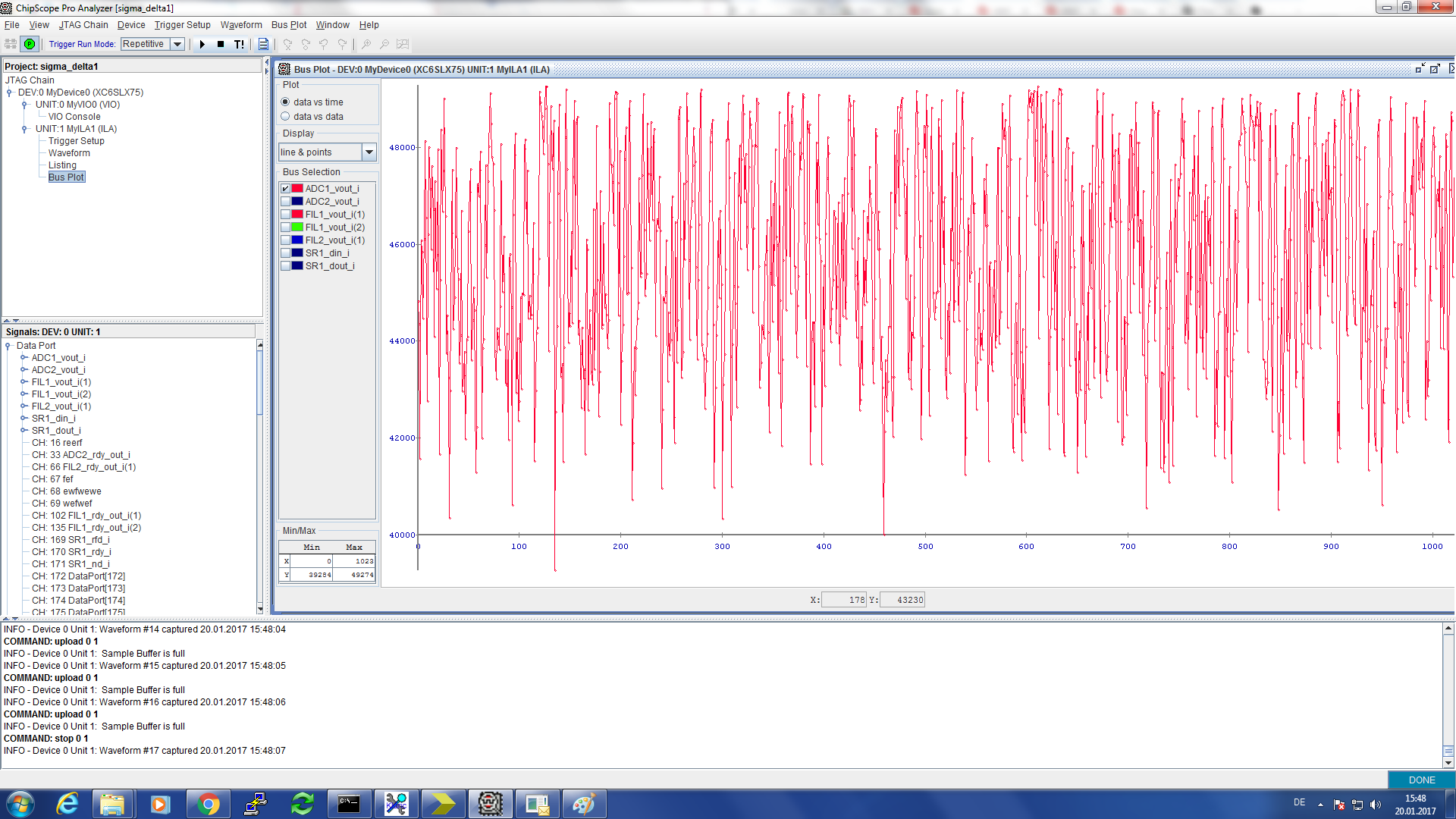
after the implementation of the filter we should see a signal with some noise. All we get is noise for any input signal. Is there an example code to implement in an FPGA?