This thread has been locked.

If you have a related question, please click the "Ask a related question" button in the top right corner. The newly created question will be automatically linked to this question.

ADS41B25EVM: ADC data seems to be wrapping around

Part Number: ADS41B25EVM
Other Parts Discussed in Thread: ADS41B25, LMK61A2-125M00EVM

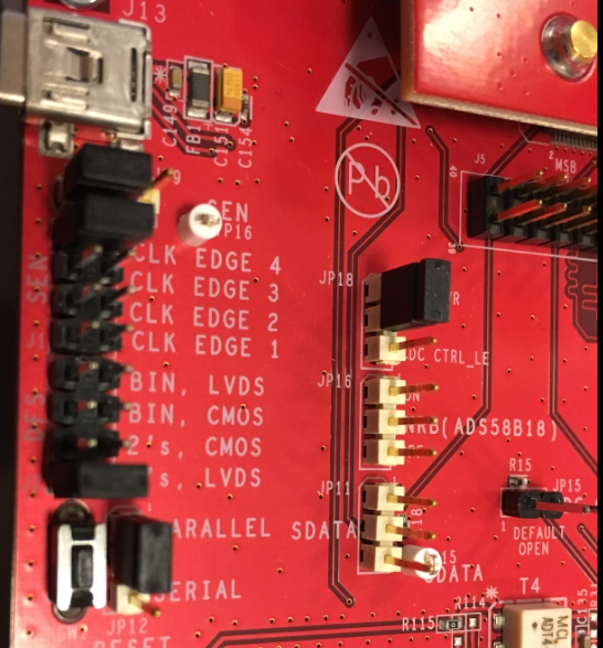
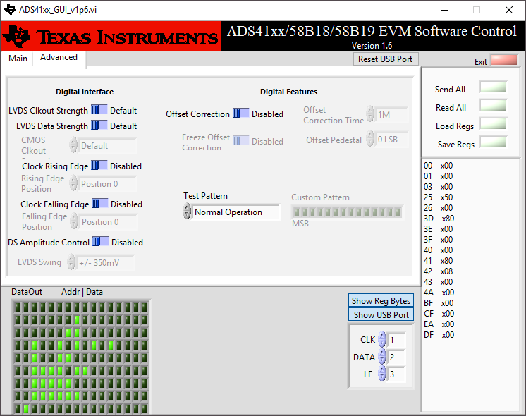
I am testing a ADS41XX/58B18EVM (ADS41B25) board with an Altera MAX 10M50D Evaluation board, though a HSMC-ADC-BRIDGE Rev. C1 interface board.

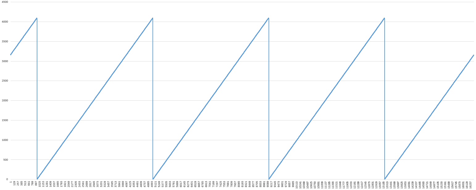
When sampling a sine wave the signal seems to wrap around.

What could be causing this?

  • Jacob,

    Change the output format (2's complement or unsigned binary) of either the ADC output or the capture card input so the two match.

    Regards,

    Jim 

  • I have already tried setting the ADC for both of those in turn. It doesn't seem to make any difference. For the peak samples of the sine wave, the values for the peaks cross each other for the positive and negative half periods, which leads me to believe that something else is wrong.

    When looking at the binary pattern of the peak 3-4 samples, they have opposite MSB of the remaining samples of the same half period.

    If I subtract the full-scale value from the negative half periods, the sinus becomes normal, but how could I choose which samples to subtract from in the time domain, when I can't base it on the value of the sample...

    These waveforms show very clearly how the signal is wrapping around. What I don't understand is how this is happening. I'm displaying 12-bit values from a 12-bit ADC.

  • [double post]

  • Jacob,

    The only way I can get an output similar to what you are showing, is when I switch the ADC output from Offset Binary to 2'compliment. Are you using the part in serial or parallel programming mode? If serial, can you send your register writes? If parallel, how are the jumpers configured on the board? What frequency is the sample clock? Are you using the gain feature? What is the amplitude of your analog input? Since you are using the adapter board, are you 100% sure of the FPGA mapping of the input data pins? Is there a chance these are out of order? Is there a chance you have a few signals that have the P/N swapped when they get to the FPGA? Did you enable the ramp test pattern and see what this looks like?

    Regards,

    Jim

  • Capture data with the ADC in ramp mode. This will take the front end interface out of the loop.

  • I have tried both Offset Binary and 2'compliment, and both using the jumpers and using the serial link.

    In parallel, JP9 and JP12 were in pos. 1-2, and JP11 was missing. In serial mode, all three were in pos. 2-3. I can verify in serial mode that the ADC is being configured. For example, I can set the ADC to output a test ramp.

    The clock is generated by an LMK61A2-125M00EVM, so 125 MHz.

    I am not using the gain features of the external op-amp, nor of the ADC.

    For the sine wave, the input is 5MHz 0.5Vpp with no offset. I also tried 50mVpp with similar results. For the non-sine waveform, it is a pulse generated by 2.5V pins on the FPGA.

    I know that the adapter board swaps + and - around, so I have compensated for that in the FPGA.

    Test ramp shown below.

    If I edit the LVDS interface in the FPGA to not compensate for the switched polarities on the interface board, the signal become very different.

  • ADS41B49_serial_SPI_Test.pptxJacob,

    Take a look at the attached file. My ramp is going in the opposite direction. Not sure why the two are different.

    Regards,

    Jim

  • As a sanity check I just tried inverting the data lines and clock in all four possible combinations, one at a time.

    ADC test ramp with/without data inverted and offset binary/2s complement:

    Clock inverted, otherwise as above:

    50mVpp external sine wave with/without data inverted and offset binary/2s complement:

    500mVpp, otherwise as above:

    Now when the positive and negative half periods don't overlap, I can fix it pretty easily...

    ... but when they overlap, I can't:

    Offset binary vs. 2s complement seems to make no difference whatsoever. Nor does it really make sense to me to be the problem, since as mentioned, the peaks of the half periods do not necessarily have the same MSB as the rest of the same half period.