This thread has been locked.

If you have a related question, please click the "Ask a related question" button in the top right corner. The newly created question will be automatically linked to this question.

ADS1299: EMG Setting up and electrodes placement

Part Number: ADS1299


Hi, I'm developing a simple prototype to read EMG signals using the ADS1299 Dev KIT as a close relative has ALS, I plan to test the dev kit to see the viability to use the ads1299 on this project family funded. I'm not testing it on the patient because of the risks and the term of service so we are generating 10 to 20 mvolts to check whether the readings are right.

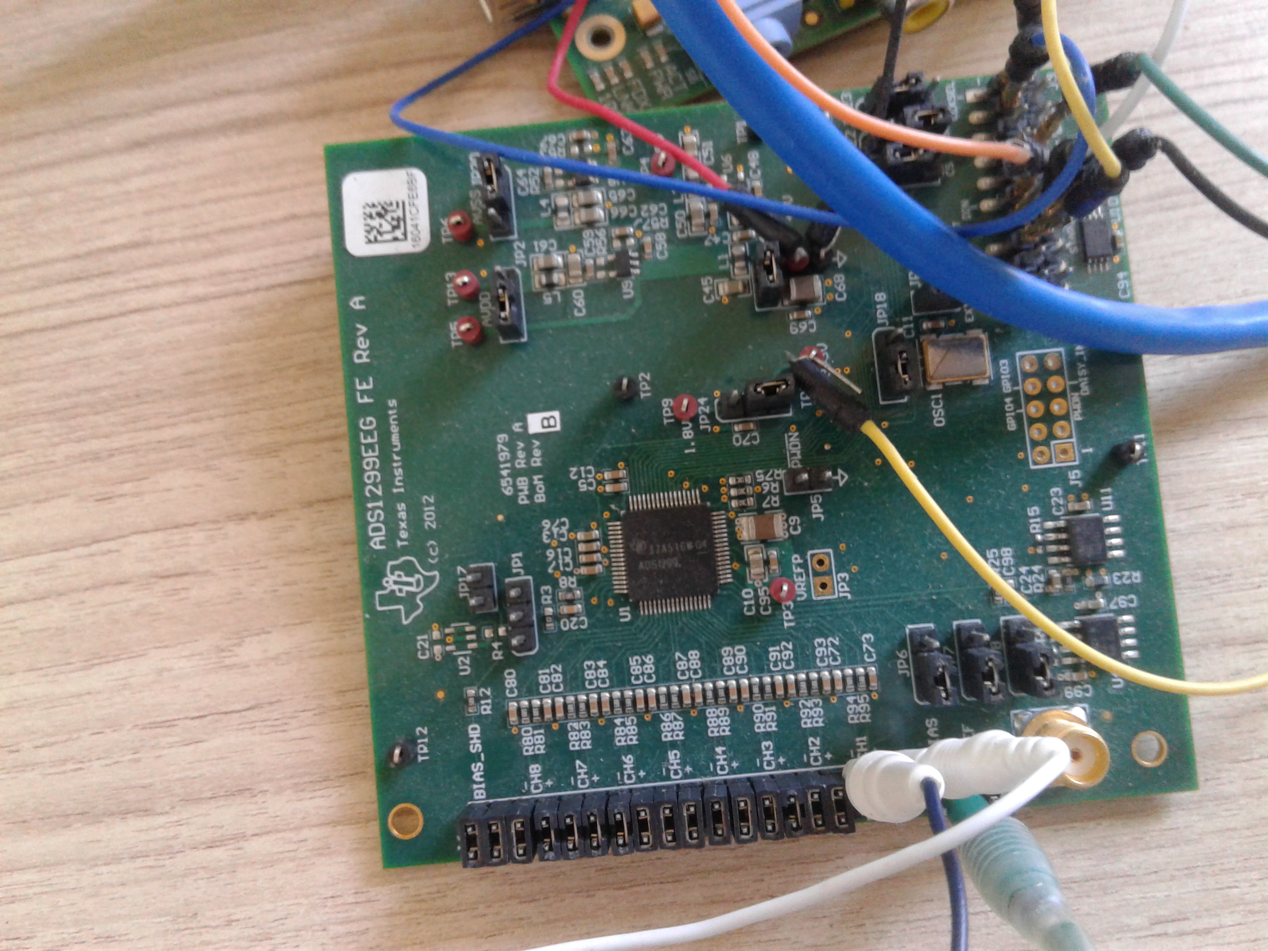
I've decoupled the bottom board and am using the top one interfaced with a raspberry.

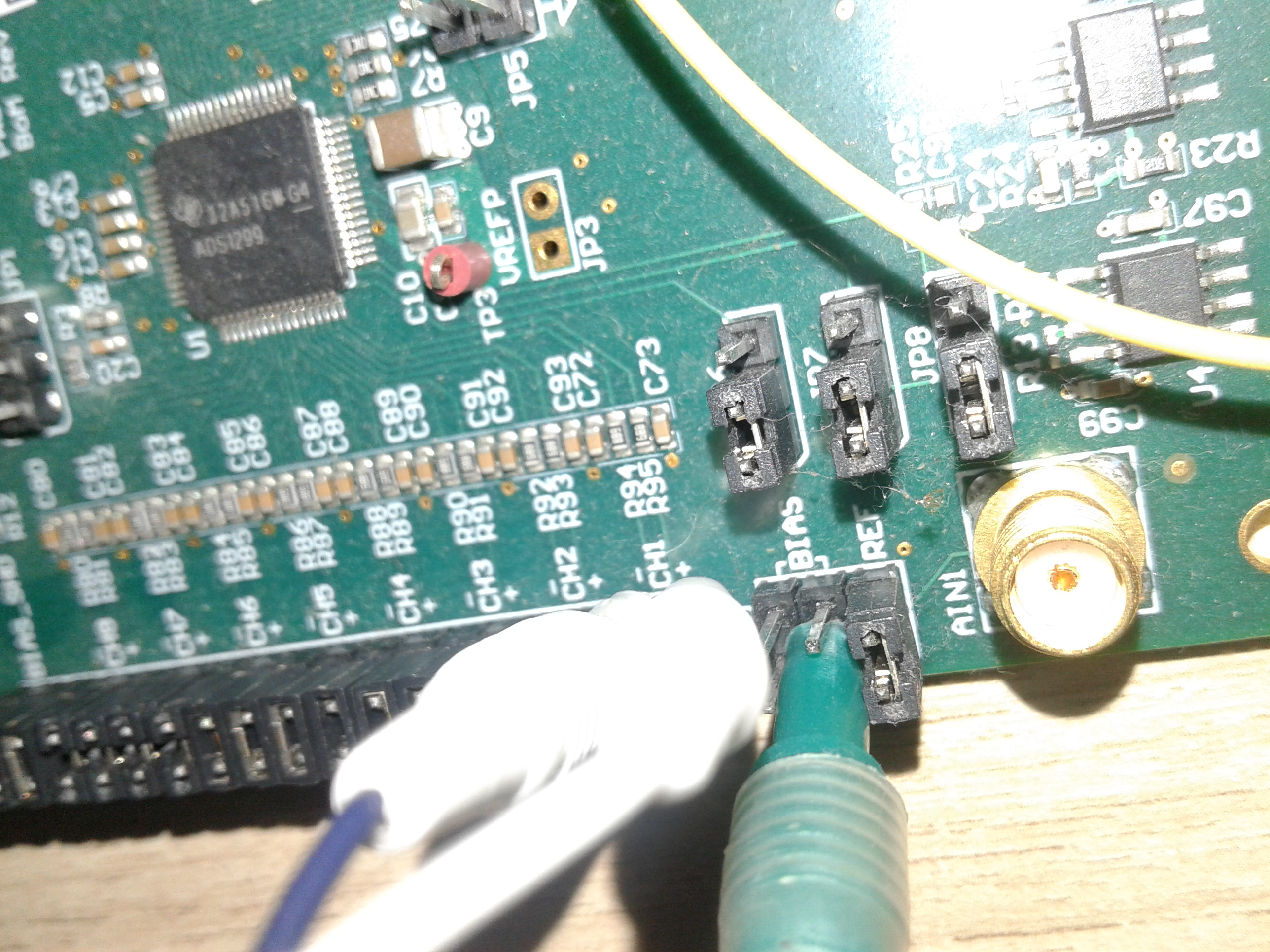
I have the SPI communication working, battery feeding working but I need some guidance on how to set up the jumpers and where to place the electrodes to optimize it for EMG not EEG.

I'm using only 3 electrodes being 1 a BIAS electrode (which I don't know where to place), 2 electrodes connected to channel 1 INP1 AND INN1.  All the other channel pins are grounded with jumpers.

So basically I just need a review if the jumpers/electrodes are in the right places? And where do I use the bias electrode (green one) ?

Thank you so much, and I'm sorry if it doesn't make sense, I never thought I'd face myself working with something so complicated :\

Im getting this usually:

Sample: 1
Status Register: 0xc00000
MOSI: 00
MISO: 80
MOSI: 00
MISO: 00
MOSI: 00
MISO: 00
Channel 1: 0x800000
MOSI: 00
MISO: 80
MOSI: 00
MISO: 00
MOSI: 00
MISO: 00
Channel 2: 0x800000
MOSI: 00
MISO: 80
MOSI: 00
MISO: 00
MOSI: 00
MISO: 00
Channel 3: 0x800000
MOSI: 00
MISO: 80
MOSI: 00
MISO: 00
MOSI: 00
MISO: 00
Channel 4: 0x800000
MOSI: 00
MISO: 80
MOSI: 00
MISO: 00
MOSI: 00
MISO: 00
Channel 5: 0x800000
MOSI: 00
MISO: 89
MOSI: 00
MISO: 7c
MOSI: 00
MISO: f8
Channel 6: 0x897cf8
MOSI: 00
MISO: c4
MOSI: 00
MISO: 7e
MOSI: 00
MISO: 5c
Channel 7: 0xc47e5c
MOSI: 00
MISO: d2
MOSI: 00
MISO: f0
MOSI: 00
MISO: 57
Channel 8: 0xd2f057
MOSI: 12
MISO: 00
MOSI: 00
MISO: c0
MOSI: 00
MISO: 00
MOSI: 00
MISO: 00

Sample: 2
Status Register: 0xc00000
MOSI: 00
MISO: 87
MOSI: 00
MISO: a5
MOSI: 00
MISO: 48
Channel 1: 0x87a548
MOSI: 00
MISO: 87
MOSI: 00
MISO: a5
MOSI: 00
MISO: b0
Channel 2: 0x87a5b0
MOSI: 00
MISO: 87
MOSI: 00
MISO: 8c
MOSI: 00
MISO: 72
Channel 3: 0x878c72
MOSI: 00
MISO: 87
MOSI: 00
MISO: 88
MOSI: 00
MISO: ee
Channel 4: 0x8788ee
MOSI: 00
MISO: 87
MOSI: 00
MISO: 96
MOSI: 00
MISO: 38
Channel 5: 0x879638
MOSI: 00
MISO: 87
MOSI: 00
MISO: 90
MOSI: 00
MISO: 55
Channel 6: 0x879055
MOSI: 00
MISO: 87
MOSI: 00
MISO: 8f
MOSI: 00
MISO: 7b
Channel 7: 0x878f7b
MOSI: 00
MISO: 87
MOSI: 00
MISO: 8c
MOSI: 00
MISO: 8a
Channel 8: 0x878c8a
MOSI: 12
MISO: 00
MOSI: 00
MISO: c0
MOSI: 00
MISO: 00
MOSI: 00
MISO: 00


  • getting this from channel 1:

    2203072
    9484067
    9375437
    2693244
    3989886
    4069873
    2588166
    14063130
    9382370
    2271747
    3524891
    4569072
    10822222
    9832759
    5570920
    12419569
    1869867
    9389349
    9833378
    9571258
    3921838
    10835709
    15552582
    7065451
    6021191
    9608172
    9480769
    10144252
    11641152
    3444971
    4471987
    5434102
    10568913

    Applying the formula ((($CHANNEL_READ * 0,000000268)*2) -4,5 ) results in accordingly for a random signal ranging from 0mv to 20mv...

    -3,319153408
    0,583459912
    0,525234232
    -3,056421216
    -2,361421104
    -2,318548072
    -3,112743024
    3,03783768
    0,52895032
    -3,282343608
    -2,610658424
    -2,050977408
    1,300710992
    0,770358824
    -1,51398688
    2,156888984
    -3,497751288
    0,532691064
    0,770690608
    0,630194288
    -2,397894832
    1,307940024
    3,836183952
    -0,712918264
    -1,272641624
    0,649980192
    0,581692184
    0,937319072
    1,739657472
    -2,653495544
    -2,103014968
    -1,587321328
    1,164937368

    Have no clue if it is right? :O

  • Hi Rodrigo,

    Thanks for your post!

    You're on the right track by using a signal source with known, reliable output as a starting point. Make sure that the common-mode voltage (Vcm) is within the acceptable input range of the PGA (see equation 4 on page 23 of the datasheet). Typically, it's easiest to set this to mid supply. The differential voltage (between INxP and INxN) can swing around Vcm from +Vref/Gain to -Vref/Gain. In a real-world application, this is the purpose of the BIAS electrode, which drives the body with a DC bias voltage in addition to a common-mode mode cancellation signal.

    We are more than happy to review your register settings and EVM jumper configuration as you evaluate the ADS1299; however, since we really are not the medical experts, we cannot provide any guidance on the best electrode placement for your application (most of our customers know this much better than we do :) ).

    If you can provide your data in an x-y plot format with units labeled on the axes, it would be much easier to interpret the data you are collecting.

    Best Regards,