Because of the Thanksgiving holiday in the U.S., TI E2E™ design support forum responses may be delayed from November 25 through December 2. Thank you for your patience.

This thread has been locked.

If you have a related question, please click the "Ask a related question" button in the top right corner. The newly created question will be automatically linked to this question.

WAVESN-BRD-5.1 & ADC10DV200EB. Can not get any input signal.

Other Parts Discussed in Thread: WAVEVISION5, ADC10DV200

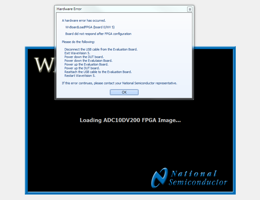
There are some error messages show up on Wavevision5 when I opened the program.

Here is the picture of entering to the program and the error messages.

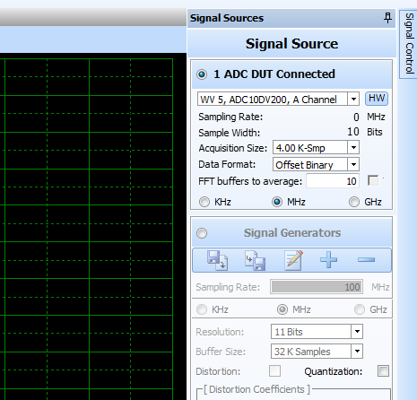
After going to the program I tried to search the evaluation board again by clicking the button at Siganl Sources-->HW. 

Here is the picture after the host compurter and the board are connected.


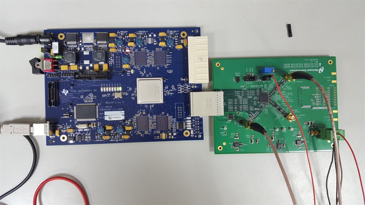
And the borad configuration is as following.

The clock signal is 0V ~ 1.8V  at 20MHz

The channel A signal is sinewave 0V~0.8V at 50kHz

The reference voltage  is 1V.

Power supply for evaluation borad is 5V.

The LED1, LED11,LED19 are on.

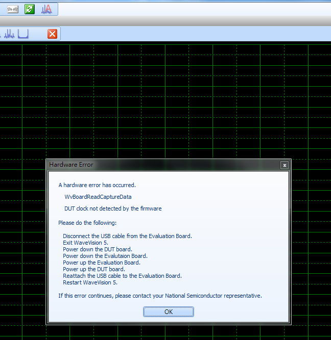
And I tried to click "acquire data from the current signal source" it shows the error message as following.

Dose anyone know where did I do wrong or did I set anything wrong?

  • Hi Wei

    Please note that per the datasheet the ADC10DV200 has a minimum input clock rate of 65 MHz when operated in LVDS Output Mode with DCS (duty cycle stabilizer) on. This is the configuration of the EVM.

    The 20 MHz clock you are using is lower than any of the ADC configurations possible. The EVM can only be operated in LVDS mode, so even with DCS disabled the minimum clock frequency is 45 MHz.Try with a clock frequency of at least 65 MHz and let us know if the behavior changes.

    Please also note that the signal path on the EVM is optimized for signals > 70 MHz. You will need to try a high input frequency once you get the board functioning properly.

    Best regards,

    Jim B

  • Hi Jim

    Thank you for your response. I really appreciate it.

    Here is my board new configuration.

    *******************************************************************************
    The clock signal is 0V ~ 1.8V at 70MHz

    The channel A signal is sinewave 0V~0.4V at 70MHz (Only for EVM funtioning properly)

    The reference voltage is 1V.

    Power supply for evaluation borad is 5V.
    ********************************************************************************

    Unfortunately the problems still stay exactly same. There is no any behavior changes after I speed up clock to 70MHz.

    Here is the picture of power supply and function generator.


    Before the clock source is on the current shows on the power supply is 0.16A. After the clock source is on the current become 0.2A. Next, I feed the 70MHz input signal and the current become 0.21A. Last I open the data capture board and turn on the program trying to connect the EVM to computer then the current turns into 0.23A.

    Hope this little information would help.

    Best regard,

    Wei

  • The problem is still unsolved.

    Hope there is an update soon.
  • Hi Wei

    The ADC10DV200EB is tested with a clock frequency of 200 MHz and a clock generator output power of +19dBm. Please try to locate a generator capable of that frequency and output power and see if the EVM will operate correctly under those conditions.

    Best regards,

    Jim B

  • Hi Wei

    I received an ADC10DV200EB and did some testing.

    With 200 MHz Fclk and 70 MHz Fin I am able to get data captures at the expected performance level.

    I did have problems with the initial startup of the board and had to follow one extra step to get a successful connection to the board and data captures.

    Here is the procedure to try:

    1) Turn on the 5V power to the ADC10DV200EB and turn on the power switch to the Wavevision5.1 capture board.

    2) Turn on the 200 MHz clock source.

    3) Launch Wavevision5 software, after loading the FPGA image the error message will pop up.

    4) Close Wavevision5 software, but leave all power and signals applied to the board.

    5) Launch Wavevision5 software. This time the software should load and recognize the board and no error message will be displayed.

    6) Click on the Capture button to get a buffer of data into the software. The data values should be toggling near mid-code for the 10b converter. On my board I see codes 506 and 507.

    7) Apply an input signal and click capture. Adjust input amplitude and frequency as needed.

    This presentation file shows the results of my testing.

    /cfs-file/__key/communityserver-discussions-components-files/73/1524.ADC10DV200EB-startup.pdf

    Best regards,

    Jim B

  • Hi Wei

    I also tried testing with lower clock frequencies.

    The lowest clock frequency I have successfully captured data at is 120 MHz. I think there is a limitation in either the FPGA data capture firmware, or the EVM clock path that is preventing captures at lower clock frequency.

    Best regards,

    Jim B