This thread has been locked.

If you have a related question, please click the "Ask a related question" button in the top right corner. The newly created question will be automatically linked to this question.

DAC161S997: spi communication with DAC161S997

Part Number: DAC161S997
Other Parts Discussed in Thread: ENERGIA

Hello everyone
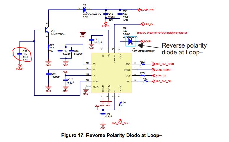
i'm having problems with making the DAC161S997 working properly. My design is the same as in the typical application in the datasheet of the device, but the communication with the device isn't working well, i have the oscilloscope decoding well the commands on the MOSI line but the DAC still not providing the correct value of the current in the loop. Is there any special manipulation with the SPI to make it work ??
every help is welcome :)

  • Howdy Manai and welcome to the e2e forums! :)

    The SPI write is composed of 24 clock cycles, with the first 8 bits being the command byte, and the last two bytes being the data information. Can you verify this frame structure? Additionally, you may need to check that the SPI clock phase and polarity is set correctly in your microcontroller platform -- data presented on the SDI lines are latched into the device on the rising edge of SCLK, pg 10 of DS.

    If possible please publish an oscilloscope capture of a complete SPI transaction, this will allow us to verify if timing requirements are met.

    Best Regards,
    Matt
  • Thank you for the answer
    yes i have checked the clock polarity and phase(SPI mode 0 or 3) and i'm sanding 3 SPI transactions (using SPI.transfer from the energia software, i.e. 24 clock cycles and using the correct data format : 8bits command and 16bits data) and i have managed to make it write the correct values of current for the range from 15mA to 20mA but when i want to write a value below 15mA it start floating betwin the value of 3mA and 4mA. Is there any reason for that ??
  • Manai,

    That sounds very similiar to the alarm current functionality of the device.  As reported in page 9 of the DS, the DAC161S997 "reports faults to the plan controller by forcing the OUT current into one of two error bands. The error current bands are defined as either greater than 20mA or less than 4mA.  Loop errors are reported by setting current of ERR_LOW."

    By default, ERR_LOW is set for 0x24, which corresponds to approximately 3.37mA on pin OUT.

    Using this information, it may be safe to assume that there is an issue with communication or the current loop in your application. Please provide register readback of the following registers:

    STATUS Register: 0x09 or 0x7F

    This register provides status of Loop Error and SPI Timeout error.

    Best Regards,

    Matt

  • unfortunately the DAC161S997 doesn't respond to the SPI commands, either for writing the desired current value or for reading internal registers( spaciallay the STATUS register). Besides the SPI specifications(24 clock signals and the data format) is there any special manipulation with it ?
  • Thank  you Matthew Sauceda for your help.

    problem solved !!!!

    The DAC161S997 now is responding to every current value that i send and it is functioning properly. The problem was this capacitor in the base of the transistor and the loop- in the design of the 2-wire transmitter of TI designs () after i have removed it everything is normal.

    Best Regards,

    Oussema

  • Howdy Oussema,

    That's great news!  It may be a typo in literature, but when in doubt always refer to the datasheet :)  The datasheet does state that the capacitance on the BASE pin should not exceed 20pF (pg 22 of the DS), as anything larger may affect the stability of the system.

    Best Regard,

    Matt