This thread has been locked.

If you have a related question, please click the "Ask a related question" button in the top right corner. The newly created question will be automatically linked to this question.

DAC3283EVM: Differential DC-coupled analog signals of DAC3283EVM & ADS4149EVM ?

Part Number: DAC3283EVM
Other Parts Discussed in Thread: FMC-DAC-ADAPTER, , FMC-ADC-ADAPTER, ADS4149EVM, THS4509EVM, THS4509, LMP8350

Hi,

I'm interested in combinations of DAC3283EVM + FMC-DAC-Adapter & ADS4149EVM + FMC-ADC-Adapter with Xilinx ZC706 Dev. board.

There are some requirements on our design.

Both analog input & output type are differential and DC-coupled.

However, DAC3283EVM and ADS4149EVM support single-ended transformer-coupled analog signals.

I know that removing transformer and installing SMA connector are the solution for differential DC-coupled analog signals.

But, I don't know the exact way for them.

Please explain circuit revision method to me.

BR.


  • Seungik,

    You will need to modify the DAC EVM as follows:

    1. Remove T1, T2, R137, R153, R155, R156.

    2. Install R109, R134, R135, R136, R6, R15, R20 and R27.

    For the ADC EVM, do the following:

    1. Remove R84, T1, T2.

    2. Install J8, R82, and short across pads 4-3 and 6-1 of both T1 and T2. For a DC coupled setup, swap out C69 and C68 with 0 Ohm resistors. R23 and R24 need to be removed if the external signal has the correct required common mode applied for the ADC.  

    Regards,

    Jim   

  • Hi, Jim.

    Thank you for your answer.

    I have a question of your answer.

    What means 'R23 and R24 need to be removed if the external signal has the correct required common mode applied for the ADC' ?

    Additionally, do you know that how IOUTA1 & IOUTA2 (current) of DAC3283EVM should be converted into voltage?

    Is further signal conditioning circuitry for I/V conversion required?

    I'll be waiting for your answer :D

    Best regards,

    Seungik Cho.

  • Seungik,

    The pullup resistors on the DAC EVM will convert the output to a voltage. What exactly will the DAC be driving?

    For the ADC, the VCM output of the ADC will connect to the pos/neg inputs with R23 and R24 installed. By default, the EVM has the ADC setup for AC coupling and this connection is required to set the Pos/Neg inputs to the correct VCM for the ADC.

    Regards,

    Jim 

  • Hi, Jim.

    The pullup resistors on the DAC EVM will convert the output to a voltage. What exactly will the DAC be driving?

    -> I'm designing certain CAN communication system.

    -> CAN bus is implemented through transmission line terminated with 120-ohms resistors at either end.

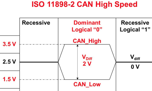
    -> Common-mode voltage of this application is 2.5V and differential swing voltage is 2Vp-p.

    -> I will attach a picture related with my application.

    -> Can some FDA EVMs such as THS4509EVM be used? also How can I drive DAC3283EVM? 

    For the ADC, the VCM output of the ADC will connect to the pos/neg inputs with R23 and R24 installed. By default, the EVM has the ADC setup for AC coupling and this connection is required to set the Pos/Neg inputs to the correct VCM for the ADC.

    -> So, I need to scale common-mode voltage & differential swing voltage of ADC input signals down so that it meet ADC spec. 

    -> I'm worried about this.


    Please give me some advices.


    Best regards,


    Seungik Cho.


  • Seungik,

    You possiblly could use the on-board THS4509 to drive the ADC. What will be feeding the input to this ADC EVM? Is it some device operating the ISO 11898-2 spec? Will this be a differential input signal? I do not know anything about this standard and the website wants to charge for downloading this.

    What will the output of the DAC be connected to? A system level block diagram showing all of the hardware and interface specs will be helpful. 

    Regards,

    Jim

  • Thanks.

    What will be feeding the input to this ADC EVM? What will the output of the DAC be connected to?

    -> The output of D/A EVM is equal to specification of above referenced picture. The output swing as referenced single-ended is maximum 3.5V & minimum 1.5V.

    Its differential signal has range of 0V - 2V.  .

    I am considering LMP8350, which supports output swing requirements on my design.

    (In HP mode, LMP8350 supports maximum 4.18V & minimum 0.82V) 

    But, no LMP8350EVM is.

    Are there any alternative product?