This thread has been locked.

If you have a related question, please click the "Ask a related question" button in the top right corner. The newly created question will be automatically linked to this question.

ADC081C027: Programming the ADC081C027

Part Number: ADC081C027
Other Parts Discussed in Thread: TCA9535

 I am trying to program the ADC081C027, but I am not able to get any results from any register, but the default settings. Even using i2cset and i2cget I am unable to set or change any values on any of the internal registers.

sudo i2cget -y 1 0x51 0x00, which should give me the conversion result in a hex formate gives me only 0x00

I also trying to set the configuration register using 

sudo i2cset -y 1 0x51 0x02 0x20 to set the conversion interval to 32 and flags to 0 and polarity to 0

then,

sudo i2cget -y 1 0x51 0x02, which still gives me 0x00

So nothing I'm doing is chaining the values on the device

here is the python code I was writing to interface with the device, but it is not working:

#import CHIP_IO.GPIO as GPIO
import time
import smbus

#I2C Address
ADC081C027_ADDRESS= (0x51)#is U1 and 0x51 is U9

#Internal Registers
ADC081C027_CONVERSION_RESULT = (0x00)
ADC081C027_ALERT_STATUS = (0x01)
ADC081C027_CONFIG = (0x02)
ADC081C027_LOW_LIMIT = (0x03)
ADC081C027_HIGH_LIMIT = (0x04)
ADC081C027_HYSTERESIS = (0x05)
ADC081C027_LOWEST_CONVERSION = (0x06)
ADC081C027_HIGHEST_CONVERSION = (0x07)


class ADC081C027:
    def __init__(self, twi=1, addr=ADC081C027_ADDRESS):
        self._bus = smbus.SMBus(twi)
        self._addr = addr
        self._bus.write_byte_data(ADC081C027_ADDRESS,ADC081C027_CONFIG,0x20)#set Converstion Interval to 32, set flags to 0, set polarity to 0


    def rawvoltage(self):
        volt=self._bus.read_i2c_block_data(ADC081C027_ADDRESS,ADC081C027_CONVERSION_RESULT)#Read from conversion result return whole string, only getting 0x00
        return volt

    def typeofTrip(self):
        flag=self._bus.read_i2c_block_data(ADC081C027_ADDRESS,ADC081C027_ALERT_STATUS)#Return type of trip either 01 or 10
        return flag


    def setLowVolt(self, lim):
        self._bus.write_byte_data(ADC081C027_ADDRESS,ADC081C027_LOW_LIMIT, lim)#Set low voltage for flag on conversion register

    def getLowVolt(self):
        result=self._bus.read_i2c_block_data(ADC081C027_ADDRESS,ADC081C027_LOW_LIMIT)#Get low voltage set before
        return result

    def setHighVolt(self, lim):
        self._bus.write_byte_data(ADC081C027_ADDRESS,ADC081C027_HIGH_LIMIT, lim)#Set High voltage for flag on conversion register

    def getHighVolt(self):
        result=self._bus.read_i2c_block_data(ADC081C027_ADDRESS,ADC081C027_HIGH_LIMIT)#get high voltage set before
        return result

    def setHysteresis(self,hyst):
        self._bus.write_byte_data(ADC081C027_ADDRESS,ADC081C027_HYSTERESIS, hyst)#set hyst on conversion register

    def getHysteresis(self):
        result=self._bus.read_i2c_block_data(ADC081C027_ADDRESS,ADC081C027_HYSTERESIS)#get hyst set before
        return result

    def getLowestConverstion(self):
        result=self._bus.read_i2c_block_data(ADC081C027_ADDRESS,ADC081C027_LOWEST_CONVERSION)#get lowest conversion
        return result

    def getHigestConverstion(self):
        result=self._bus.read_i2c_block_data(ADC081C027_ADDRESS,ADC081C027_HIGHEST_CONVERSION)#get highest conversion
        return result


and the code to run it:

import voltcheck
import relay
import time


zonelist=[1,0,0,0,0,0,0,0,0,0,0,0,0,0,0,0]#change any of 16 values to turn on or off zone
tca9535 = relay.TCA9535()
tca9535.byzone(zonelist)
#This is to enable a relay and create an closed circuit to get the voltage from


upperLim=0x05
lowerLim=0x01
hysteresis=0x00
adc081C027 = voltcheck.ADC081C027()

print "test for voltage on relays, load limits and wait for it to be met"
adc081C027.setLowVolt(lowerLim)
print "lower set to " + str(lowerLim)
time.sleep(.1)

adc081C027.setHighVolt(upperLim)
print "upper set to " + str(upperLim)
time.sleep(.1)

adc081C027.setHysteresis(hysteresis)
print "hysteresis set to " + str(hysteresis)
time.sleep(.1)

print "raw volatage" + str(adc081C027.rawvoltage())

print "low range was " + str(adc081C027.getLowVolt())
print "high range was " + str(adc081C027.getHighVolt())
print "hysteresis was " + str(adc081C027.getHysteresis())
print "lowest conversion on record is " + str(adc081C027.getLowestConverstion())
print "highest conversion on record is " + str(adc081C027.getHigestConverstion())


Thanks for any help,
Vijit Singh

  • Hello Vijit,
    Could you please upload also a schematic of your setup of the device and its interface connections? That would help us to debug this issue.
    Thanks,
    Vishy
  • Vijit,
    SDA and SCK are open drain pins and need a pull up resistor (5k) to the supply. I don't see them in the schematic above. Could you double check it's there? The address selected (0x51) looks right.
    Thanks,
    Vishy
  • There are 2.4k resistors I forgot to add this page.

  • Thanks. I see the resistors 209, 210. Looks like there's also another device (TCA9535) on the i2c bus through the level shifter U57. I am wondering if the level shifter is working properly. Did you probe and check on the scope you see proper I2C waveforms (correct slave address) when you initiate a read or write on TW11_SCK and TW11_SDA pins? Do you get an ack from the adc? Could you please upload I2C transaction scope shot ?

    Thanks,
    Vishy
  • Hi Vishy,

     Sorry for the delay of response I had to wait till I could get a hold of an oscilloscope, here are my scope shots for sudo i2cget -y 1 0x51 0x00 it is in two frames:

    This is the scope shot of sudo i2cset -y 1 0x51 0x02 0x20:

    Thanks for the help,

    Vijit Singh

  • Vijit,

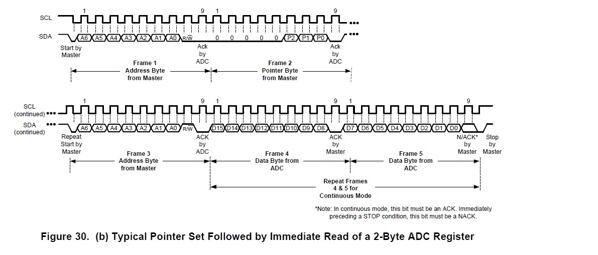
    Address 0x0 is a 2-byte register. So for a read operation (i2cget), it should be totally 5 frames. See figure below

    Reading your first scope shot, Frame 1 data is 0xA2 (device address 0x51 shifted left 1 bit plus write bit), Frame 2 is 0x00 (pointer byte 0x0), Frame 3 is 0xA3 (device address shifted left 1 bit plus read bit), Frame 4 is 0x01 and there is no Frame 5. Please check i2cget: this function has to read 1 more byte to see the complete 16-bit data. 

    Thanks,

    Vishy

  • Vishy,
    Now I am reading 16bits and getting the following when setting the conversion interval to 000, 001, 010, etc:

    chip@chip:~$ sudo i2cset -y 1 0x51 0x02 0x00
    chip@chip:~$ sudo i2cget -y 1 0x51 0x00 w
    0x1000
    chip@chip:~$ sudo i2cset -y 1 0x51 0x02 0x20
    chip@chip:~$ sudo i2cget -y 1 0x51 0x00 w
    0x3000
    chip@chip:~$ sudo i2cset -y 1 0x51 0x02 0x40
    chip@chip:~$ sudo i2cget -y 1 0x51 0x00 w
    0x2000
    chip@chip:~$ sudo i2cset -y 1 0x51 0x02 0x60
    chip@chip:~$ sudo i2cget -y 1 0x51 0x00 w
    0x2000
    chip@chip:~$ sudo i2cset -y 1 0x51 0x02 0x80
    chip@chip:~$ sudo i2cget -y 1 0x51 0x00 w
    0x2000
    chip@chip:~$ sudo i2cset -y 1 0x51 0x02 0xA0
    chip@chip:~$ sudo i2cget -y 1 0x51 0x00 w
    0x2000
    chip@chip:~$ sudo i2cset -y 1 0x51 0x02 0xC0
    chip@chip:~$ sudo i2cget -y 1 0x51 0x00 w
    0x2000
    chip@chip:~$ sudo i2cset -y 1 0x51 0x02 0xE0
    chip@chip:~$ sudo i2cget -y 1 0x51 0x00 w
    0x1000

    I'm writing these hex values by using 0000 0000 for 000, 0010 0000 for 001 and so on because the first three bits on 02 are for the conversion interval and the following five are for Alert Hold, Alert Flag Enable, etc.

    the outputs are changing the reserve portion on 0x00 which should always be 0000, but the conversion result the middle two bits are staying 0. For example when I set the conversion interval to 000, which is Mode Disable, I am reading 0x1000 on 00 the conversion result which in binary is 0001 0000 0000 0000. The reserve pins on the Conversion result register are changing, but not the result. The reserve pins are changing and not staying 0 based on what I setting the conversion interval too on 02.

    Which conversion interval should I be using and why are the reserve bits changing and not the conversion result bits?

    I have not changed any of the other registers from their default value.
  • Vijit,
    Since we are still debugging i2c read/write: Suggest you please verify simple register read and write are working properly. Device has both 1 byte and 2 byte registers. So you have to check you are able to do reliably 1 byte read/write and 2 byte read/write.
    a) Configuration register (address 02h) is a 1 byte register. Please do a i2c write (say 0x68) and read back (1 byte) the configuration register and check if you get the value you wrote. Try different values and make sure this is working reliably.
    b) Alert Limit Register (address 04h) is a 2byte register. Please check if you are able to write some known value (say 0x0A5A) and read the value back. Here again, please try multiple times with different values and verify read/write code is working without issue.

    Appreciate if you could upload scope shots for 1byte and 2byte read/write. That's the one I can double check to make sure setup and code is working.

    Thanks,
    Vishy

  • Vishy,

    Here is what I got:
    a)
    chip@chip:~$ sudo i2cset -y 1 0x51 0x02 0x68
    chip@chip:~$ sudo i2cget -y 1 0x51 0x02
    0x68
    chip@chip:~$ sudo i2cset -y 1 0x51 0x02 0x70
    chip@chip:~$ sudo i2cget -y 1 0x51 0x02
    0x70
    chip@chip:~$ sudo i2cset -y 1 0x51 0x02 0x80
    chip@chip:~$ sudo i2cget -y 1 0x51 0x02
    0x80
    chip@chip:~$ sudo i2cset -y 1 0x51 0x02 0x64
    chip@chip:~$ sudo i2cget -y 1 0x51 0x02
    0x64
    seems to be reading and writing properly

    b)
    chip@chip:~$ sudo i2cset -y 1 0x51 0x04 0x0A5A w
    chip@chip:~$ sudo i2cget -y 1 0x51 0x04 w
    0x0a0a
    chip@chip:~$ sudo i2cset -y 1 0x51 0x04 0x0A50 w
    chip@chip:~$ sudo i2cget -y 1 0x51 0x04 w
    0x0a00
    chip@chip:~$ sudo i2cset -y 1 0x51 0x04 0x5555 w
    chip@chip:~$ sudo i2cget -y 1 0x51 0x04 w
    0x5505
    chip@chip:~$ sudo i2cset -y 1 0x51 0x04 0x8bc2 w
    chip@chip:~$ sudo i2cget -y 1 0x51 0x04 w
    0x8b02

    Here the third value is always being set to 0 regardless of what I set it too. I will try to get scope shots as soon as possible.

    Thanks,
    Vijit
  • Heres the shot for sudo i2cset -y 1 0x51 0x02 0x68:

    shot for sudo i2cget -y 1 0x51 0x02:

    shot for sudo i2cset -y 1 0x51 0x04 0x0A5A w:

    shot for sudo i2cget -y 1 0x51 0x04 w:

  • Vijit,

    Please check implementation of this command
    i2cset -y 1 0x51 0x04 0x0A5A

    Reading your scope shot for this command, Frame 1 data is 0xA2 (device address 0x51 shifted left 1 bit plus write bit), Frame 2 is 0x04 (pointer byte 0x4), Frame 3 is 0x5A , and Frame 4 is 0x0A. So the 2 data bytes are getting swapped and not getting written in proper order.

    Also, check the 16-bit get function: I think there also data read may be getting swapped.

    Thanks,
    Vishy