


Hello everyone.
Got some questions about ADC12j4000 digital down converter.
While looking through datasheet I've found FIR-filters coefficients used in DDC (Table 9 at p. 36).
Decided to have my own try to model these filters in MATLAB software.
As it said in Table 8. at p.35, for Desimation Setting equal to 4, it uses cs19 and cs55 cascade.
Here is short MATLAB code for modeling that:
c19 = (1/(2*16384))*[22 0 -174 0 -2429 0 10029, 16384, 10029, 0 -2429 0 -174 0 22];
c55 = (1/(2*262144))*[-37 0 118 0 -291 0 612 0 -1159 0 2031 0 -3356 0 5308 0 -8140 0 12284 0 -18628 0 29455 0 -53191 0 166059 ...
262144 166059 0 -53191 0 29455 0 -18628 0 12284 0 -8140 0 5308 -3356 0 2031 0 -1159 0 612 0 -291 0 118 0 -37];
c19f= dsp.FIRDecimator('DecimationFactor',2,...
'NumeratorSource','Property',...
'Numerator', c19,...
'Structure', 'Direct form');
c55f = dsp.FIRDecimator('DecimationFactor',2,...
'NumeratorSource','Property',...
'Numerator', c55,...
'Structure', 'Direct form');
c19c55 = dsp.FilterCascade(c19f,c55f);
fvtool(c19c55);
And that's a MATLAB response:

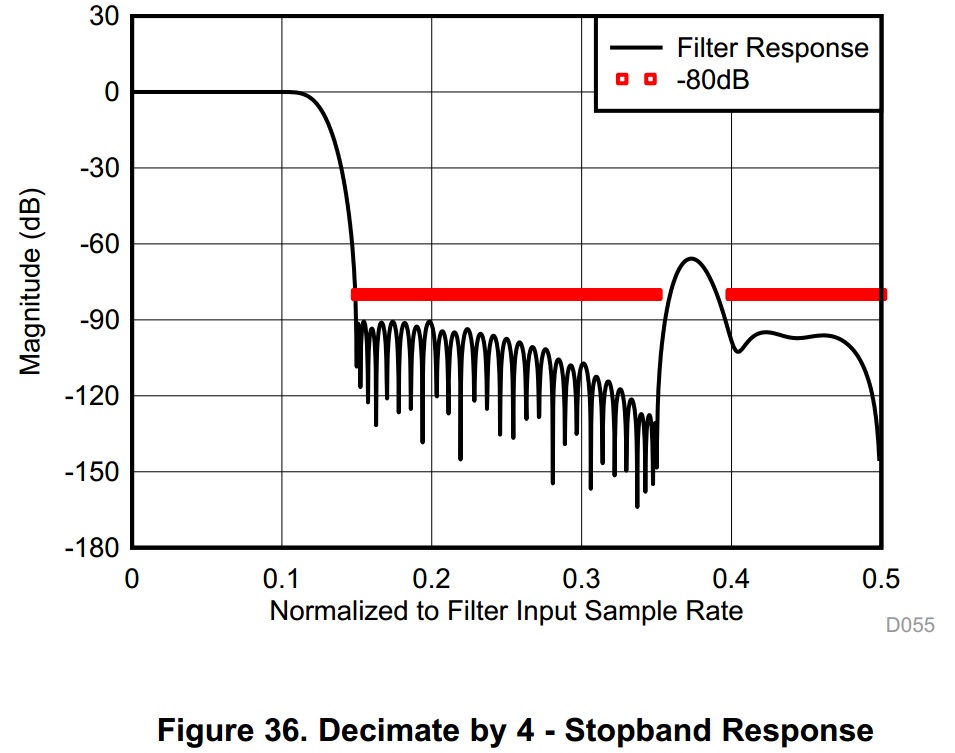
And the problem is that it differs much from filter's perfomance, given in datasheet (Figure 36, p.23):
Could anyone help me with this? Probably I'm doing something wrong.
If there exist a full MATLAB or Simulink model of ADC(not necessary exactly that one ADC) with DDC, it would great if you share it.

