This thread has been locked.

If you have a related question, please click the "Ask a related question" button in the top right corner. The newly created question will be automatically linked to this question.

ADS1210: A/Dcovert value is shift

Part Number: ADS1210

Hi,

My customer is using ADS1210.
He has a issue.
It is A/D covert value is shift at being high temperature.
The input differential voltage (AINP-AINN) is 0.193V.
In case of 25 degrees, convert value is "4B4477h".
In case of 45 degrees, convert value is "491B80h".
This is big deference.

At first, I want to confirm circuit.
Especially, it is the circuit of input part.
Customer uses BIAS pin.
Does this circuit have problem?

Best regards,
Shimizu

  • Hi Shimizu,

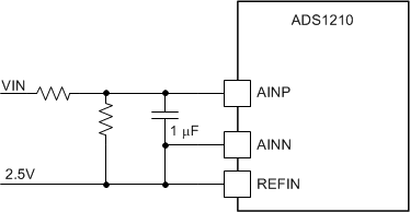
    Can you share the actual input voltage applied?  Also, can you please send the Command register settings?  Schematically the input is configured as pseudo-differential where the AINN input is fixed at 1/2 of VBIAS.  VBIAS will be approximately 3.3V for a 5V AVDD and the AINN input at 1.65V.  AINP cannot go below GND, so the lowest practical input voltage is -3.3V where AINP would then equal 0V.  So for the time being I will assume that the input is +/- 3.3V.

    There are two potential issues with the circuit as presented.  One is the amount of analog settling time at the inputs using 10k resistors and 1uF cap.  The second is resistor drift.  You need a stable input voltage and the resistor dividers must stay in balance.  For this circuit to work well low drift precision resistors must be used.

    Another possible connection, depending on the drive capability of the reference, is to use the reference instead of the VBIAS.  You could connect the 2.5V reference directly to the AINN input. The AINP voltage divider would connect to the 2.5V reference as well.  The advantage is a more stable bias and fewer components.

    Best regards,

    Bob B

  • Hi Bob,

    Thank you for your support.

    >Can you share the actual input voltage applied? 

    Please see below.

    >Also, can you please send the Command register settings? 

    Please see below

    Is this using situation problem?

    Best regards,

    Shimizu

  • Hi Shimizu,

    Thanks for the information.  There is a potential issue relative to the 10k resistors and the actual input impedance of the ADS1210. With maximum gain, the input impedance is reduced significantly to around 250k ohm.  If the resistors are not well matched, there can be a significant offset error created.  Also, there can be an error due to the voltage drop across the input resistors relative to the input impedance.  I see from the configuration that a Pseudo-System calibration is done.  What happens in this case is a system offset calibration (for 0V input) is conducted and then a self-gain calibration.  This only happens once and takes place when the configuration is written to the MD bits.  Based on the codes you gave from the initial post, the voltage calculates out to be 182.51mV for 25 deg C and 177.27 for 45 deg C.  In neither case does the output code match the 193mV input.

    I believe there may be a couple of issues with the results.  The first is the system offset is not being correctly calculated.  When the Pseudo-System calibration is issued, the AINP input must be at 0V.  For the offset to be correctly calculated, a 0V input must be applied.  This should correct for any initial resistor differences.

    There could also be an issue with the reference both with initial accuracy and temperature stability.  This would appear as a gain error.  Can you tell me what is used to generate the reference?  If over temperature the output of the reference increases slightly the codes will lower as the voltage representation for a single code will change.  Has the reference voltage been measured both at 25 deg and 45 deg C?

    Another potential issue, as I stated in my last post, is the initial accuracy and temperature stability of the resistors used in the bias circuit. Also, the value of the resistors relative to the input impedance can also be a factor.  Can you give me specific details on the resistors used for the 10k ohm resistors for the bias circuit?  Has smaller resistor values been tried to see if this makes a difference?

    Is it important to use the bias circuit?  Will negative voltages be applied?  What is the expected range of input voltages to be applied to the input?

    Best regards,

    Bob B