This thread has been locked.

If you have a related question, please click the "Ask a related question" button in the top right corner. The newly created question will be automatically linked to this question.

DAC8551: is it the right DAC?

Part Number: DAC8551
Other Parts Discussed in Thread: DAC80004, DAC7678, DAC8571

Hi everyone,

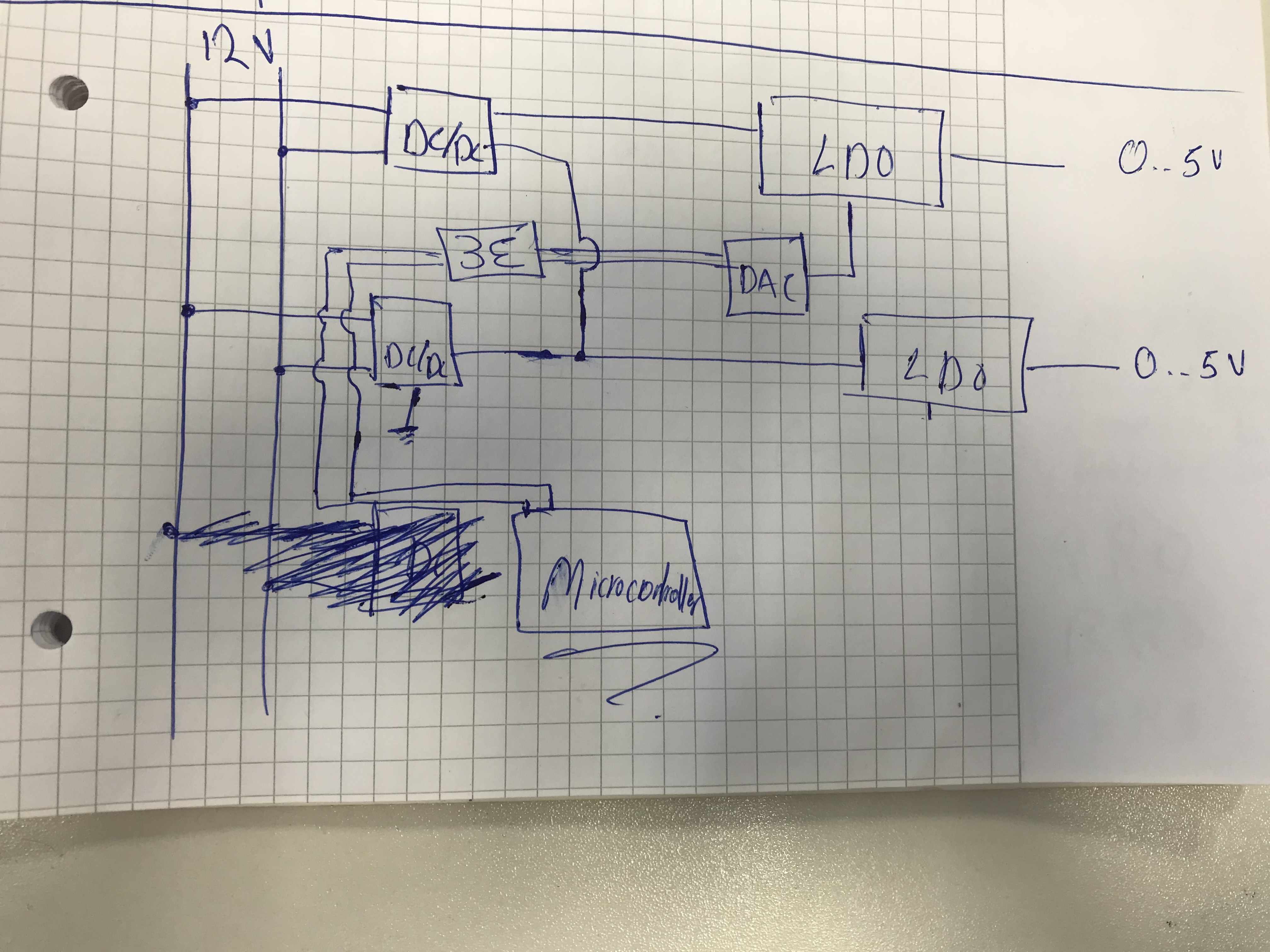
i have a small question i need to use a 16-Bit DAC for a battery design and connect it to my LDO to control my output voltage. between 0 and 5 Volt.

After the researches i found that DAC8551 is the accurate and suitable one for my design, i might be wrong, what are the actual ones now and the best one to use?

i want the best accuracy, less noise, good voltage between 0 and 5 Volt.

And a small question also what would be the easiest microcontroller to control my 16-DAC.

I appreciate your answers thanks.

Regards,

Fadi

  • Hi Fadi,

    Welcome to E2E and thank you for your query. You can look into the following blog for the design guidelines for your application:

    e2e.ti.com/.../give-your-voltage-regulator-the-margin-it-deserves

    I think you can go with DAC8551 if you need only one channel output. There are other higher channel DACs like DAC80004 as well in case you need better performance.

    You can use any microcontroller with an SPI interface. Usually, the controllers have up to 16-bit SPI frame formats - you can use a GPIO as the CS pin for getting 24-bit or 32-bit frames required by the DACs.

    Hope I have answered your question.

    Regards,
    Uttam Sahu
    Applications Engineer, Precision DACs
  • Hi Uttam,

    Yes you did, thanks alot :)

    Regards,

    Fadi
  • Hi Again Uttam,

    I checked out this, its helpful with designing the circuit for the LDO and DAC, but i have a small difference here. i will have like 6 LDOs and 6 Dacs, the thing is my LDOs and 6 dacs are connected to eachother in parallel and have only one ground, basically in the link you gave me for the video with GPIO, each LDO has its own ground.

    Do you know how i can solve this?
  • Hi Fadi,

    Can u draw your requirement as a block diagram so that I am able to visualize it properly? The link doesn't talk about multiple grounds as I know. I am not sure which video you are taking about.

    Regards,
    Uttam
  • I am speaking about this video here training.ti.com/voltage-regulator-margining-precision-dacs
    which is related to the post you mentioned.

    i will send now my circuit design.
  • Here is the block diagram i hope it's clear and sorry for the mess. basically i will have this like 16 multiple Times representing 16 simulated cells.

    the things is that they are connected to eachother. and in the end to one ground.

    Regards,

    Fadi

  • Hi Fadi,

    I am trying to understand your requirement but not fully clear. If I am not wrong, you want LDO outputs that are stacked up with the previous ones. Could you please provide me the following details so that I can propose a suitable solution:

    1. What is the output from each DC-DC converter?
    2. What are the number of stages? I think you mentioned 6. Correct me if I am wrong
    3. The LDO output is 0-5V with respect to the building up on the adjacent one. Correct me if I am wrong
    4. What is the adjustable voltage range by the DAC, with and without an isolator between the uC and DAC?
    5. Is this the only architecture in your mind? Can you go with a simple architecture where you can use LDO's with different ranges? What do you want to achieve finally?


    Regards,
    Uttam
  • 1. 9 Volt ( i will use a flyback converter )
    2. lets say 20 stages instead of 6, so i will have 20 DACs and 20 DC-DC and control them with a microcontroller.
    3. True not more than 5v and should be adjustable to 0 ( i think i found the right component for this ).
    4. it should be less or equal to 1mv ( really accurate)
    5. most important is to get output voltage from 0 .. 5 V for 20 stages ( 20 simulated cells) and lets say a bit of current i can measure like 500mA. i would be glad if you have a similiar solution instead of having 20 flyback converters and 20 Dacs. What i wanna achieve is a simulation cells i can do measurments on them and connect other systems on them. i wanna be able to read those values later on choose the cell .. etc.
  • Also btw i wanna communicate with DAC and Microcontroller with I2C, i think the DAC8551 don't have I2C.
  • Hi Fadi,

    If you want to create a generic solution and make the system stackable, and

    1. the DAC ground is connected to the respective LDO ground,
    2. the DAC supply and ground are isolated from the common circuit ground through an isolator,

    you can go with the design guideline we were taking about.

    You can look at DAC7678 for this application for meeting the I2C interface requirement.

    Regards,
    Uttam
  • HI again :)

    Thanks for your replay, the DAC you mentioned is not so accurate, what would you recommend? i think i should atleast have 14-Bit or 16 Bit, ROR, I2C, Low power.

    Regards,

    Fadi

  • Hi Fadi,

    You can go for DAC8571. Please note that if you are using multiple same devices on the I2C bus, there may be address contention, in which case, you will need to use external I2C buffers or something similar.

    Regards,
    Uttam