This thread has been locked.

If you have a related question, please click the "Ask a related question" button in the top right corner. The newly created question will be automatically linked to this question.

DAC8554: Total Unadjusted Error Calculation

Part Number: DAC8554
Other Parts Discussed in Thread: ANALOG-ENGINEER-CALC

Hi All

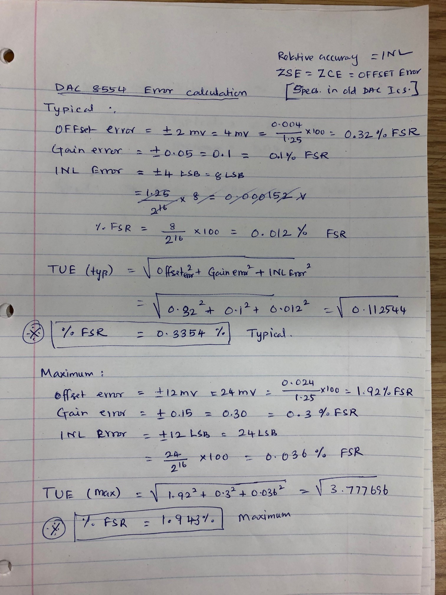
Can anyone please help me to calculate the Total Unadjusted Error for DAC8554 chip?

I could not find the INL error and Offset error information from IC datasheet. 

My design has 0-1.25V as DAC output voltage and it gets amplified to 0-10V range.

Your help is highly appreciated.

  • Hello,

    INL sometimes also goes by the name "Relative Accuracy" in some older products which is the case for this device as well.

    Sometimes some older datasheets also use the terms zero-code error (or zero-scale error) and offset error interchangeably. The most consistent way to tell the difference is if the specification is with all 0's loaded into the DAC data register or if it is a line of best fit extrapolated from two codes in the linear region of operation. That is the case for this DAC, so here zero-scale error is the offset error.

    You can find both terms on Page 2 of the datasheet.

    Concerning TUE analysis, I would point to the following blog post:
    e2e.ti.com/.../dac-essentials-how-accurate-is-your-dac
  • Hi Duke

    Thank you very much for your response. I made this error calculation based on the datasheet. Could you please verify and confirm if this is correct?

    Thank again for your support.

  • Rajkumar,

    Largely your unit conversion procedure looks correct, the only thing is about how some of the specifications have been interpreted. You do not need to extrapolate +/-2mV into 4mV for example. The specification is indicating that the offset could be either 2mV high or 2mV low, but the deviation from ideal will always be within 2mV so you do not need to expand this to 4mV. Similar is true for gain and INL errors.

    Basically then each TUE calculation would be divided by two. So 0.1677% FSR typical and 0.9718% FSR maximum.

    One of the other caveats about these old datasheets is understanding how to apply the top line conditions. Basically each specification is for operating temperatures from -40C to 105C. So the typical number of 0.1677% FSR is the room temperature behavior and the maximum value is the worst case over the whole operating temperature range.

    I should have also pointed out a tool we have on TI.com in my first reply as well, apologies for that. There is a LabVIEW based calculator one of my colleagues put together which will do the unit conversion for you. The download is a bit large due to the LabVIEW run-time engine but there are several other useful tools bundled in that GUI which you may find helpful.

    That tool is available here: http://www.ti.com/tool/ANALOG-ENGINEER-CALC

  • This is a good explanation for analyzing the DAC accuracy. Thanks for sharing the calculator link. I find this forum very very useful for clarifying any technical questions.